A dust removal and feeding device for a grain color sorter
A technology of dust removal device and color sorter, which is applied in application, food science, food processing, etc. It can solve the problems of poor color sorting effect, achieve good wiping effect, and high efficiency of conveying and wiping
- Summary
- Abstract
- Description
- Claims
- Application Information
AI Technical Summary
Problems solved by technology
Method used
Image
Examples
Embodiment 1
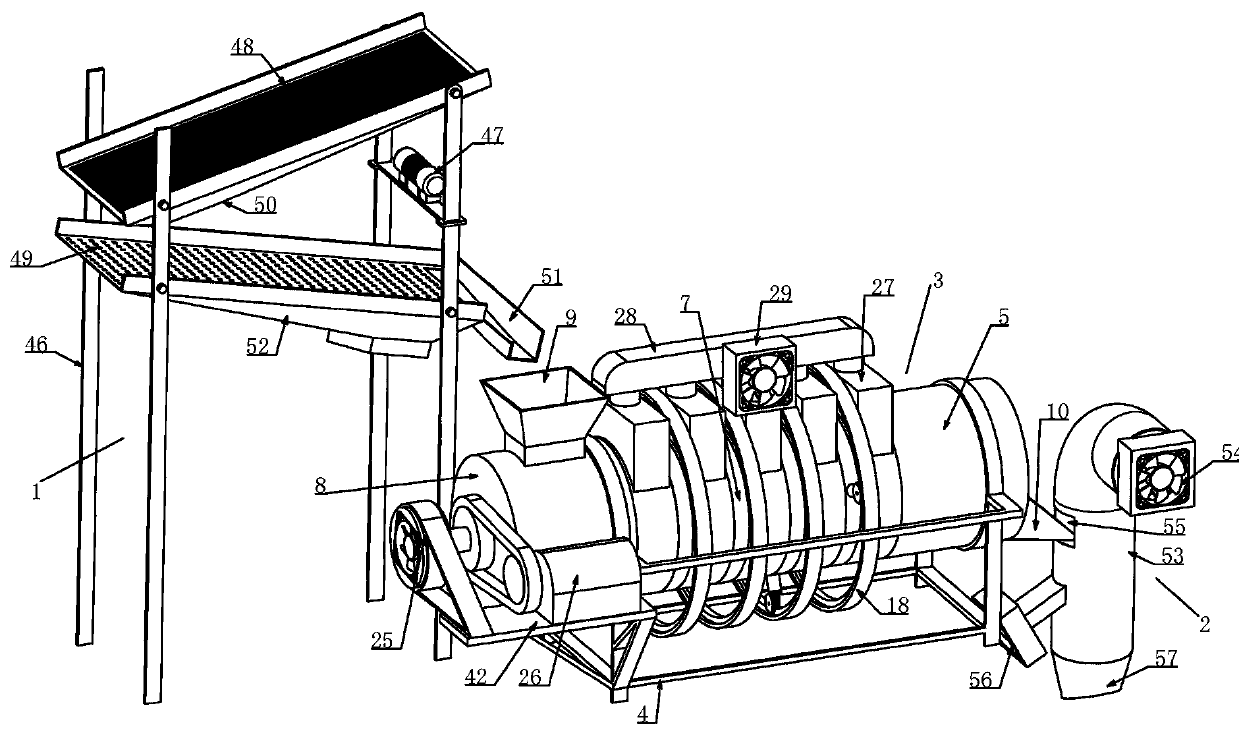
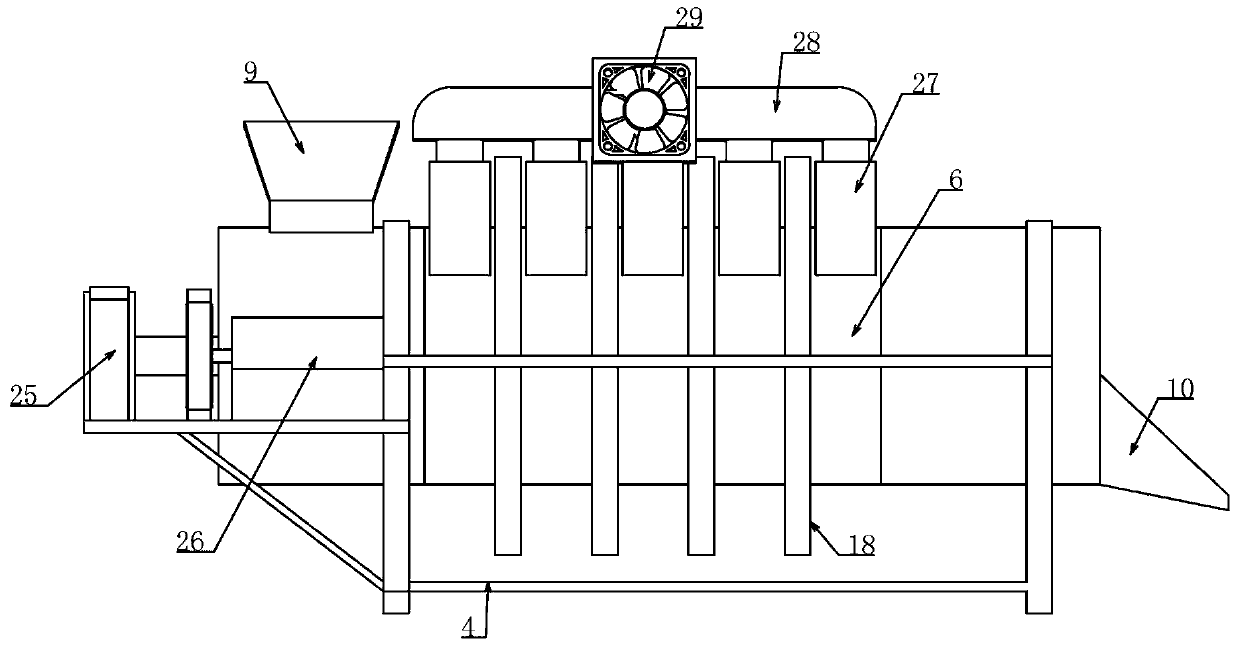
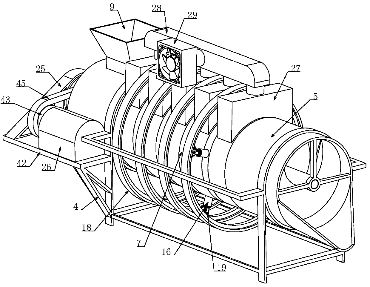
[0032] Embodiment 1, the technical solution that it solves is, a kind of grain color sorting machine uses dust removal and unloading device, comprises vibrating dust removal device 1, wind power dust removal device 2, is characterized in that, also includes conveying cleaning device 3, described conveying cleaning device 3 includes a conveying cylinder 5 supported by a bracket 4, the conveying cylinder 5 is composed of a plurality of conveying sleeves 6 arranged at intervals in the transverse direction, a sliding fit on the end of the conveying sleeve 6 for connecting two adjacent conveying sleeves 6 The connecting ring 7 is composed of a sealing cover 8 placed at the left end of the conveying sleeve 6 on the left side to make it closed. The upper part of the left side of the conveying cylinder 5 is equipped with a receiving hopper 9 for receiving the materials conveyed by the vibrating dust removal device 1. The lower hopper 10 for feeding the wind dust removal device 2 is ins...
Embodiment 2
[0036] Embodiment 2, on the basis of Embodiment 1, an annular chute 30 is formed on the end of the delivery sleeve 6 at both ends of the connecting ring 7, and the two ends of the connecting ring 7 protrude from the ring chute respectively. Annular slip ring 31 in 30. Preferably, a first sealing ring may be fixed at the end of the delivery sleeve 6 inside the annular chute 30 , and the other end of the first sealing ring is slidingly fitted with the annular slip ring 31 . The connecting ring 7 and the delivery sleeve 6 at both ends are rotated and sealed so that the airflow in the delivery tube 5 will not flow out from the connection between the connection ring 7 and the delivery sleeve 6 . Guaranteed wind pressure. The ring gear 18 can be fixed on the delivery cylinder 5 or on the bracket 4 .
Embodiment 3
[0037] In Embodiment 3, on the basis of Embodiment 1, the free end of the hollow sleeve 16 is connected to the extension rod 15 via a first sealed bearing 32 to form a structure of sealed and rotational fit. Alternatively, a second sealing ring is fixed on the inner circular surface of the free end of the hollow sleeve 16 , and the second sealing ring is sleeved on the extension rod 15 and is slidably matched with the extension rod 15 . The free end of the hollow sleeve 16 is tightly fitted between the extension rods 15, so that the air flow will not flow out from the end of the hollow sleeve 16, ensuring that the air flow enters the delivery cylinder 5.
PUM
 Abstract
Description
Claims
Application Information
 - Generate Ideas
- Intellectual Property
- Life Sciences
- Materials
- Tech Scout
- Unparalleled Data Quality
- Higher Quality Content
- 60% Fewer Hallucinations
Browse by: Latest US Patents, China's latest patents, Technical Efficacy Thesaurus, Application Domain, Technology Topic, Popular Technical Reports.
© 2025 PatSnap. All rights reserved.Legal|Privacy policy|Modern Slavery Act Transparency Statement|Sitemap|About US| Contact US: help@patsnap.com


