
Gas-liquid microreactor, device, system and method

A technology of micro-reactors and reactors, applied in chemical instruments and methods, chemical/physical/physical-chemical reactors, chemical/physical/physical-chemical processes, etc., can solve the problem of difficult to generate phase boundary area, gas-liquid stratified flow , unfavorable reactions and other issues, to achieve the effect of less processing difficulty, increase the contact area of ​​the two phases, and enhance mass transfer and mixing

Inactive Publication Date: 2019-08-23
HIMILE MECHANICAL MFG +1
View PDF0 Cites 6 Cited by
  • Summary
  • Abstract
  • Description
  • Claims
  • Application Information

AI Technical Summary

Problems solved by technology

According to the knowledge of the inventors, the flow state in the current microreactor is still dominated by direct fluid collision contact. During high-throughput gas-liquid reactions, obvious gas-liquid stratified flow is easy to occur, and it is difficult to generate sufficient phase boundary area. , is not conducive to the reaction

Method used


Image

  • Gas-liquid microreactor, device, system and method
  • Gas-liquid microreactor, device, system and method
  • Gas-liquid microreactor, device, system and method

Examples


Embodiment 1

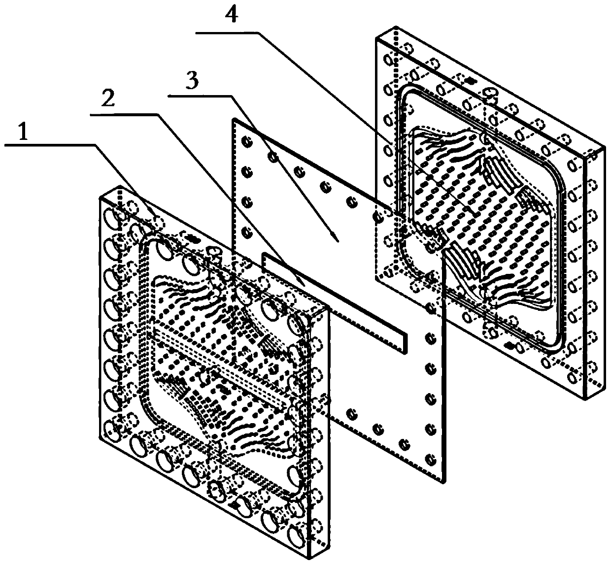
[0063] Embodiment one, such as figure 1 As shown, the gas-liquid reactor is mainly composed of a reaction plate (1), a microporous plate (2), a separator (3) and a heat exchange plate (4).

[0064] The reaction plate (1) mainly provides the reaction space. In order to ensure the effect of reaction and heat exchange, the reaction space is formed by multiple reaction channels set on the reaction plate (1). , Sealed connection, forming a closed reaction space.

[0065] Of course, in the present embodiment, the sealed connection between the reaction plate (1) and the dividing plate (3) is through a plurality of bolt holes arranged around the circumference of the reaction plate (1) and the dividing plate (3), and Bolt fixing through bolt holes. In order to ensure the sealing effect on the reaction space, a sealing ring can be arranged between the reaction plate (1) and the partition plate (3). Nice response environment.

[0066] In other embodiments, other connecting / sealing me...

Embodiment 2

[0111] Provide a more complete gas-liquid reaction device, such as Figure 6 As shown, it includes gas source, gas-liquid reactor, heat exchange device and liquid supply mechanism. Among them, the gas source supplies gas, and the gas has a certain pressure after passing through the pressurizing device, and the gas with pressure is controlled by the flow controller and then input Gas inlet B of the gas-liquid reactor;

[0112] The liquid supply mechanism supplies liquid with a certain flow rate to the liquid inlet A of the gas-liquid reactor;

[0113] The heat exchange device is connected to the heat exchange medium inlet F and the heat exchange medium outlet G of the heat exchange plate (4).

[0114] Of course, the gas-liquid reactor can also be connected with post-processing equipment.

[0115] In this embodiment, existing equipment can be used for the gas source, heat exchange device, pressurizing device, flow controller, liquid supply mechanism, etc., and will not be repe...


PUM


Abstract

The invention provides a gas-liquid microreactor. The microreactor comprises a reaction chamber and a heat exchange chamber, the reaction chamber is provided with a microporous plate, the reaction chamber is provided with at least two inlets and an outlet, gas can enter from a first inlet, and after the gas passes through the microporous plate, a microbubble flow is formed under flushing of a liquid entering from a second inlet and is discharged from the outlet; and the heat exchange chamber is provided with an inlet and a discharge outlet, and circulation of a heat exchange medium from the inlet to the discharge outlet is utilized to realize the heat exchange function and provide a temperature environment for the reaction chamber. The microreactor provided by the invention can increase acontact area of a liquid phase and a gas phase, and effectively enhance mass transfer mixing, thereby facilitating full progress of a chemical reaction.

Description

technical field [0001] The present disclosure relates to a gas-liquid microreactor, device, system and method. Background technique [0002] The statements in this section merely provide background information related to the present disclosure and do not necessarily constitute prior art. [0003] The microreactor is an important chemical process strengthening equipment. Through the tiny scale space, the mass transfer and heat transfer of the reaction are greatly improved, and the small volume also ensures sufficient safety. [0004] In traditional equipment, there are mainly three contact methods for the gas-liquid system, ① direct contact, ② the liquid phase is highly dispersed in the gas phase, and ③ the gas phase is highly dispersed in the liquid phase. According to the knowledge of the inventors, the flow state in the current microreactor is still dominated by direct fluid collision contact. During high-throughput gas-liquid reactions, obvious gas-liquid stratified flow...

Claims


Application Information

Patent Timeline
Patent Type & Authority Applications(China)
IPC IPC(8): B01J19/00
CPCB01J19/0093B01J2219/00013B01J2219/00033B01J2219/00783B01J2219/00873
Inventor 官星辰孟凡国张恭运唐立星魏猛黄振王守库魏晓张琦
Owner HIMILE MECHANICAL MFG
Learn More