
A peer-to-peer network architecture and resource location method based on DiffServ

A peer-to-peer network and differentiated service technology, applied in the field of wireless sensor networks, can solve problems such as P2P network resource management problems, P2P system resource management complexity, etc., achieve efficient and convenient positioning, and improve the efficiency of resource positioning

Active Publication Date: 2021-10-15
肇庆市华盈体育科技有限公司
View PDF5 Cites 0 Cited by
  • Summary
  • Abstract
  • Description
  • Claims
  • Application Information

AI Technical Summary

Problems solved by technology

A large number of users and massive resources make resource management in P2P networks a very challenging problem
[0005] (2) The P2P system has a strong geographical distribution: there are many users and resources in the P2P network, and each user and various resources are widely distributed geographically. The above phenomenon makes the resource management in the P2P system complicated.

Method used


Image

  • A peer-to-peer network architecture and resource location method based on DiffServ
  • A peer-to-peer network architecture and resource location method based on DiffServ
  • A peer-to-peer network architecture and resource location method based on DiffServ

Examples


Embodiment 1

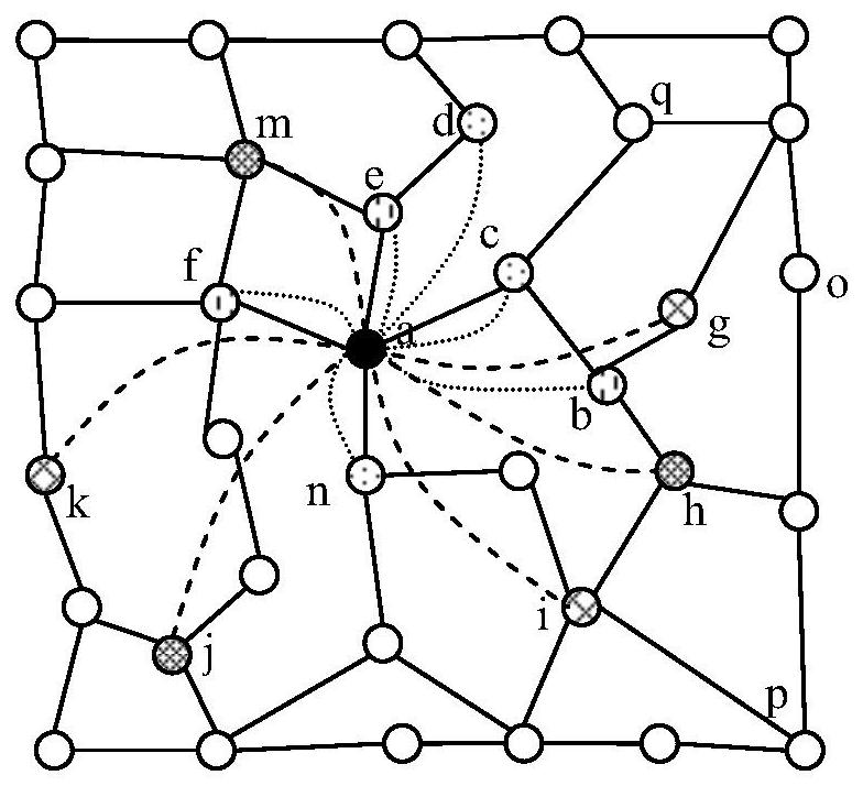
[0090] Such as figure 1 As shown, this embodiment discloses a peer-to-peer network architecture based on differentiated services, including multiple nodes such as a, b, c, d, e, f, g, etc., as shown in Table 1, each node The following two types of topologies are maintained:

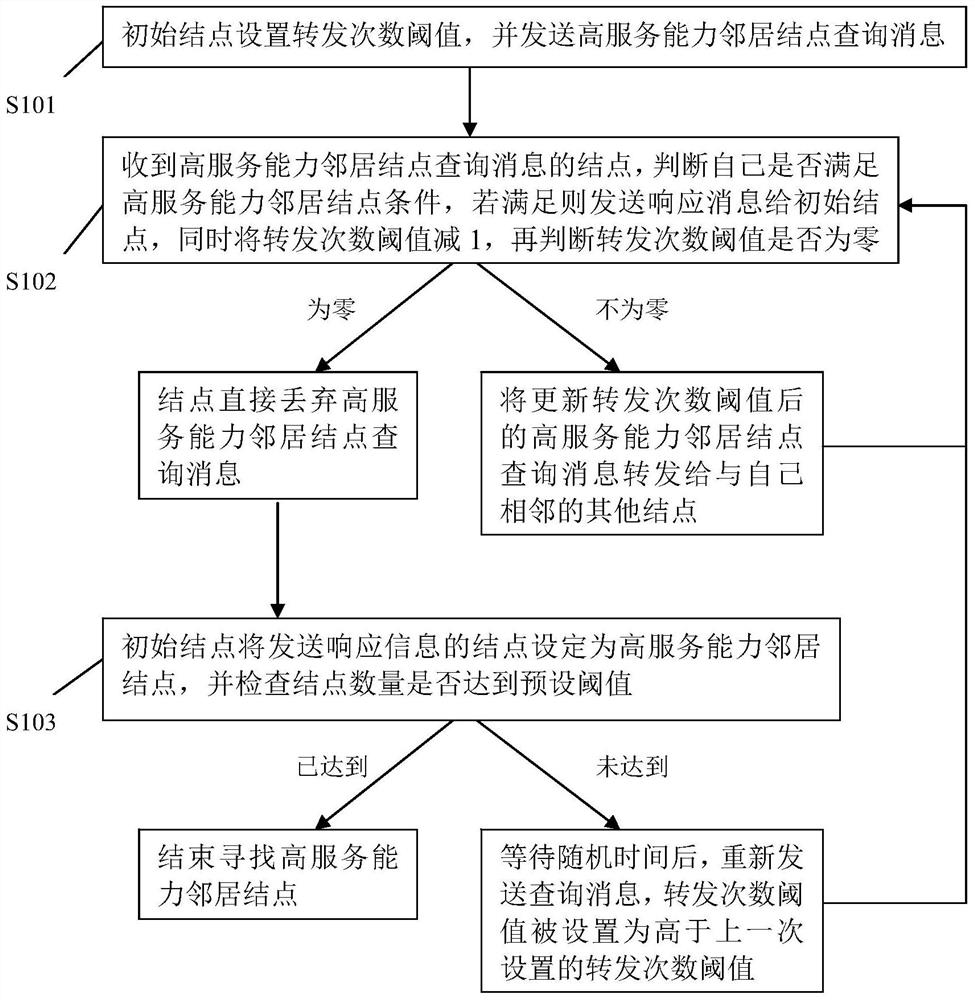
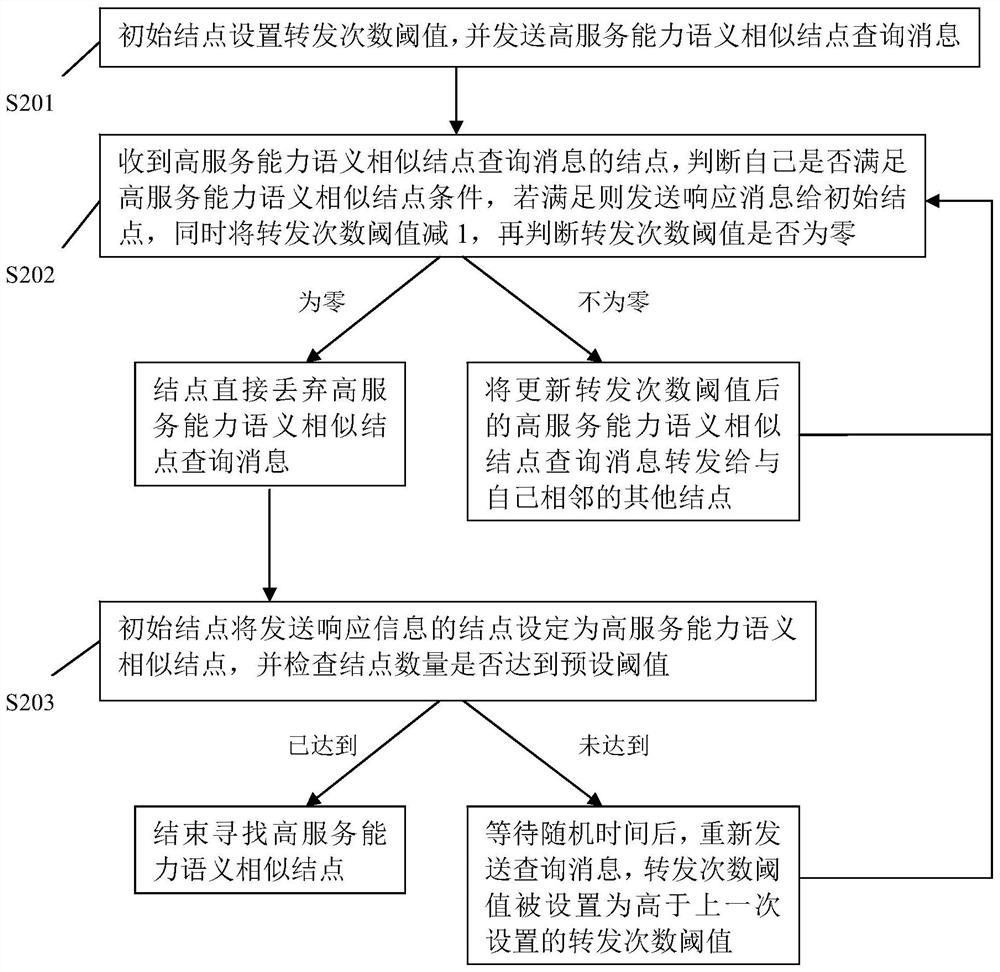
[0091] High-quality node topology, including high-serving capability neighbor node topology and high-serving capability semantically similar node topology; each node in the high-serving capability neighbor node topology and the node maintaining the topology satisfy high Neighbor node condition of service capability; high service capability semantically similar node condition is satisfied between each node in the high service capability semantically similar node topology and the node maintaining the topology; high service capability neighbor node condition is two The network distance between nodes is lower than the first preset distance, the broadband speed is higher than the preset speed, and the number ...

Embodiment 2

[0141] This embodiment discloses a resource location method based on the peer-to-peer network described in Embodiment 1 above, which is applied in such as figure 1 In the peer-to-peer network shown, the storage resources of the nodes in the network are shown in Table 2:

[0142] Node ID shared resource name Node ID shared resource name a R1_1, R1_4, R1_5, R2_1 i R1_1, R1_2, R1_5, R2_1 b R2_1, R2_2, R2_3, R3_2 j R1_2, R1_4, R1_5, R3_1 c R1_3, R2_2, R2_4, R3_3 k R1_1, R1_3, R1_5, R5_1 d R2_1, R2_2, R2_4, R3_2 m R1_1, R1_4, R1_6, R2_1 e R1_1, R2_3, R2_5, R3_5 n R2_1, R2_3, R2_4, R3_4 f R2_2, R2_3, R2_4, R3_2 o R2_1, R2_2, R2_3, R3_2 g R1_1, R1_2, R1_5, R3_1 p R1_3, R1_5, R1_6, R4_1 h R1_1, R1_3, R1_5, R5_1 q R1_1, R1_5, R1_6, R5_1

[0143] Table 2 Schematic diagram of the storage resources of the nodes in the peer-to-peer network

[0144] Such as Figure 6 As shown, this resource location...


PUM


Abstract

The invention discloses a peer-to-peer network architecture and resource location method based on differentiated services. According to the different characteristics of nodes in the network, such as broadband speed, resource quantity, network distance, semantic similarity, and online duration, the peer-to-peer The nodes in the network are composed of high-quality node topology and ordinary node topology. The two types of topology are maintained, and the service performance of the nodes is distinguished. When applied to a large and complex P2P peer-to-peer network, this technology The nodes in the network can be effectively integrated, making the topology of the nodes in the network clearer. At the same time, the invention also discloses a resource positioning method based on the peer-to-peer network, which provides users with different features according to their different resource positioning requirements. The resource location service makes the location of resources more efficient and convenient, and greatly improves the efficiency of resource location in the peer-to-peer network.

Description

technical field [0001] The invention belongs to the field of wireless sensor networks, and mainly relates to a peer-to-peer network architecture and a resource positioning method based on differentiated services. Background technique [0002] At present, with the explosive growth of information content on the Internet, the traditional client / server model does not make full use of the personal computer resources at the edge of the network, making the server overloaded and unable to meet the needs of Internet applications. In order to make full use of a large number of idle resources owned by personal computers at the edge of the network, a new application mode that can directly share and exchange resources without going through a server, that is, P2P (Peer to Peer), the peer-to-peer network was born and quickly rose and gained popularity. Wide range of applications. [0003] The P2P system has its own unique features in the application process: [0004] (1) P2P systems gene...

Claims


Application Information

Patent Timeline
Patent Type & Authority Patents(China)
IPC IPC(8): H04L29/08H04W84/18
CPCH04L67/1042H04L67/1074H04W84/18
Inventor 龚亚东王俊波
Owner 肇庆市华盈体育科技有限公司
Learn More