
Charging loop cooling structure

A cooling structure and charging circuit technology, which is applied to circuits, electrical components, insulated cables, etc., can solve problems such as difficult heat dissipation, burning of the charging connection port, poor leak-proof performance, etc., and achieve improved connection reliability, safety and reliability, and low cost. Excellent cooling effect

Pending Publication Date: 2019-08-20
SHENZHEN BUSBAR SCI TECH DEV
View PDF0 Cites 4 Cited by
  • Summary
  • Abstract
  • Description
  • Claims
  • Application Information

AI Technical Summary

Problems solved by technology

[0002] With the continuous popularization of electric vehicles, the charging equipment of this type of vehicles has become the core technology of this industry; and the charging connector of electric vehicles is an important part of the charging equipment. When charging electric vehicles for a long time, the terminals at the charging connection Because the charging current is relatively large, it will generate a certain amount of heat, and the original charging connector structure is tightly arranged, and it is not easy to dissipate heat. If the charging work is performed for a long time, the contact resistance of the charging connection terminal will increase, and the temperature rise will increase. Affect the performance of the terminal; continuous heating will also lead to the aging of plastic parts, and eventually lead to the hidden danger of burning the charging connection port; therefore, there is an urgent need to solve the heat dissipation problem of the charging connection terminal in the market. However, with the continuous development of new energy vehicles The cooling structure of the charging connection terminal can no longer meet the requirements, and the sealing of the cooling structure is poor, and the leak-proof performance is not good

Method used


Image

  • Charging loop cooling structure
  • Charging loop cooling structure
  • Charging loop cooling structure

Examples


Embodiment

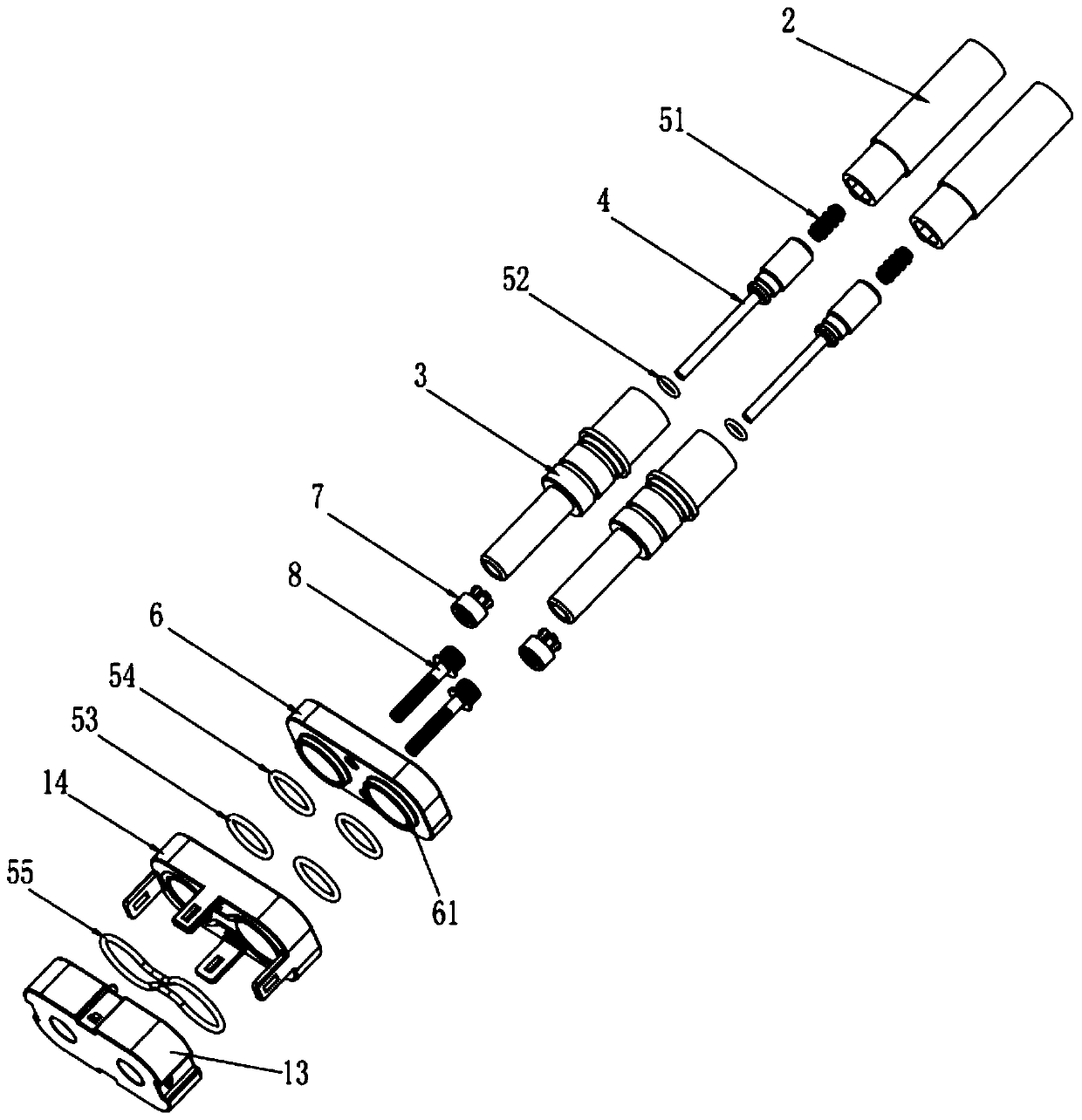
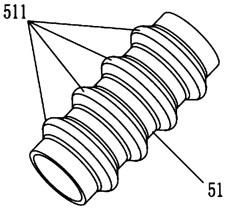
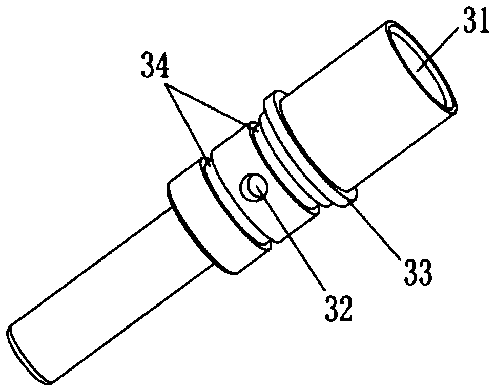
[0026] Such as Figure 1 to Figure 5 As shown, a charging circuit cooling structure shown in this embodiment includes a fixed part 1 and two jack terminals 3 sealed and penetrated in the fixed part 1 for connecting with the cable 2, and the middle of the cable 2 is provided There is a guide tube 21 for the flow of cooling medium. Specifically, the cable 2 includes a guide tube 21, a copper layer 22 and an insulating layer 23 from the inside to the outside. The rear end of the jack terminal 3 is opened in the middle of the axial direction slot 31, the slot 31 is provided with a pin 4 connected to the guide tube 21, the axial middle of the pin 4 is provided with a through hole 41 communicating with the guide tube 21, and the front end of the pin 4 extends to the groove The bottom of the hole 31, and the front end and surroundings of the pin 4 and the slot 31 are provided with a gap communicating with the through hole 41 for the flow of the cooling medium. The opposite sides of t...


PUM


Abstract

The invention discloses a charging loop cooling structure. The cooling structure comprises a fixed part and two jack terminals which are hermetically arranged in the fixed part in a penetrating mannerand are used for being connected with cables. Each cable is internally provided with a flow guide pipe used for flowing of a cooling medium. The axial middle of each jack terminal is provided with aslotted hole with an opening in one end. Contact pins connected with the flow guide pipes are arranged in the slotted holes. Through holes communicated with the flow guide pipes are formed in the axial middle portions of the contact pins. Gaps communicated with the through holes are formed between the front ends of the contact pins and the groove holes correspondingly. Flow passing holes communicated with the slotted holes are formed in the opposite sides of the two jack terminals, and flow channels communicated with the two flow passing holes are formed in the fixed part. A first sealing ringis arranged between the corresponding flow guide pipe and the corresponding contact pin, and a second sealing ring is arranged between the rear end of the corresponding contact pin and the corresponding jack terminal. The charging loop cooling structure is good in heat dissipation performance and sealing performance and has the advantages of being simple and compact in structure, safe, reliable and convenient to assemble.

Description

technical field [0001] The invention relates to the field of connectors, in particular to a charging circuit cooling structure. Background technique [0002] With the continuous popularization of electric vehicles, the charging equipment of this type of vehicles has become the core technology of this industry; and the charging connector of electric vehicles is an important part of the charging equipment. When charging electric vehicles for a long time, the terminals at the charging connection Because the charging current is relatively large, it will generate a certain amount of heat, and the original charging connector structure is tightly arranged, and it is not easy to dissipate heat. If the charging work is performed for a long time, the contact resistance of the charging connection terminal will increase, and the temperature rise will increase. Affect the performance of the terminal; continuous heating will also lead to the aging of plastic parts, and eventually lead to ...

Claims


Application Information

Patent Timeline
Patent Type & Authority Applications(China)
IPC IPC(8): H01B7/42H01R13/02H01R13/518H01R13/52H01R13/533
CPCH01B7/423H01R13/02H01R13/518H01R13/52H01R13/521H01R13/533
Inventor 林培燕徐平安黄建芳林国军
Owner SHENZHEN BUSBAR SCI TECH DEV
Learn More