Automatic ladder type fuel delivery device

A transmission device and escalator technology, applied in the field of material transmission, can solve the problems of aggravating the retention and vibration of fuel balls in pipelines, fuel loss of power source, and radioactive leakage.

Pending Publication Date: 2019-08-20
CHINERGY CO LTD
View PDF13 Cites 2 Cited by
  • Summary
  • Abstract
  • Description
  • Claims
  • Application Information

AI Technical Summary

Problems solved by technology

[0003] The existing fuel ball pneumatic conveying device has the following disadvantages: under normal working conditions, the fuel ball needs to rely on the helium compressor to provide the power source for the pneumatic conveying of the fuel ball during the pneumatic cycle transmission process, and the helium compressor is reliable. Insufficient performance leads to the loss of power source in the fuel cycle, which leads to the passive shutdown of the reactor; at the same time, in the process of pneumatic circulation transmission, there are high requirements for the internal diameter of the pneumatic transmission pipe and the inner wall of the pipe weld. and collisions, fuel dust and debris often lead to fuel ball jamming accidents, so that the fuel balls cannot be transported and circulated, resulting in passive shutdown of the reactor; the number of fuel balls in the pneumatic conveying pipeline and the size deviation of fuel balls have a great impact on the pressure parameters of pneumatic conveying Different requirements will intensify the stagnation and vibration of fuel balls in the pipeline, resulting in unstable operation of the system
[0004] Under the conditions of fuel ball jamming accidents, high temperature, high pressure, high radioactive environment and complex pipeline environment, it is difficult to find and troubleshoot fuel ball jamming points, and some jamming points cannot be reached by maintenance personnel and maintenance workers and tools, and fuel balls should be removed Jamming accidents can easily lead to radioactive leakage

Method used


Image

  • Automatic ladder type fuel delivery device
  • Automatic ladder type fuel delivery device
  • Automatic ladder type fuel delivery device

Examples


Embodiment Construction

[0018] Below in conjunction with accompanying drawing and embodiment the technical solution of the present invention is described in detail as follows:

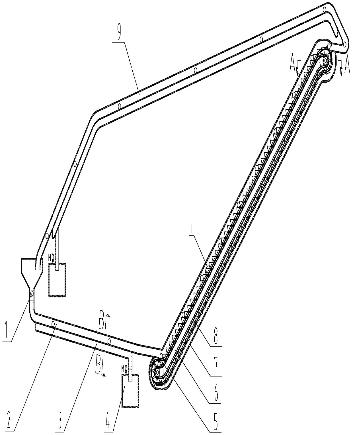
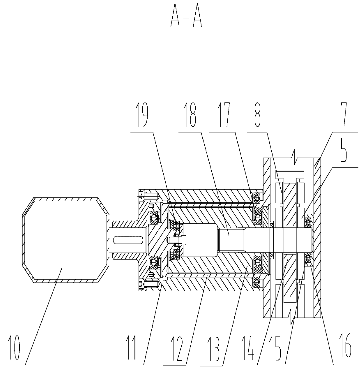
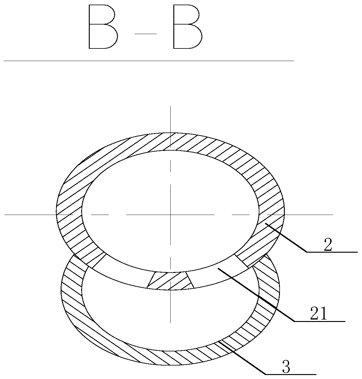
[0019] A kind of escalator type fuel transmission device of the embodiment of the present invention, see figure 1 , figure 2 , including a sealed containment body 7 containing helium, a mechanical transmission part 6 located in the containment body 7, and a drive motor 10 and a permanent magnet coupling located outside the containment body 7; the upper and lower ends of the containment body 7 are respectively connected to the gravity The passive slotted raceway (2, 9) is connected, and the bottom of the slotted raceway (2, 9) is provided with a dust conveying pipe 3 for collecting dust and debris falling through the slotted raceway. The end of the conveying pipe communicates with the dust collection device 4; the mechanical transmission part 6 includes a transmission ratchet 14, a drive chain 8 fixed on the transmission rat...


PUM


Abstract

The invention provides an automatic ladder type fuel delivery device, which comprises a sealed container for storing helium, a mechanical transmission part arranged in the sealed container, a drivingmotor, and a permanent magnet coupler, wherein the driving motor and the permanent magnet coupler are arranged in the exterior of the container. The upper end and the lower end of the container are communicated with gravity type non-active grooved raceways; the bottoms of the grooved raceways are provided with a dust delivery pipe; the tail end of the dust delivery pipe is communicated with a dustcollection device; the mechanical transmission part comprises a transmission ratchet wheel, a driving chain fixed on the transmission ratchet wheel, and multiple ladder steps fixed on the driving chain; the transmission ratchet wheel sleeves a transmission shaft; one end of the transmission shaft is fixed on the inner wall of the container through a bearing and a bearing end cover; and the otherend is arranged in the exterior of the container and is connected to the driving motor through the permanent magnet coupler. The fuel delivery device does not have any fault point, the operation is reliable, the system equipment and pipeline arrangement is simple, and moreover, the fuel delivery device can be flexibly and conveniently combined with other functional facilities and is economic.

Description

technical field [0001] The invention belongs to the technical field of material transmission, and in particular relates to an escalator-type fuel transmission device used in a high-temperature gas-cooled reactor nuclear fuel loading and unloading circulation system or petrochemical, electric power and other similar technical fields. Background technique [0002] The fuel loading and unloading cycle needs to rely on the helium compressor to provide the power source for the pneumatic transportation required for the lifting of the fuel ball. During the circulation transmission process, the fuel balls will continue to rub and collide with the unloading device, broken ball separation equipment, fuel consumption measurement equipment, bridging and other equipment, and the pipe wall. [0003] The existing fuel ball pneumatic conveying device has the following disadvantages: under normal working conditions, the fuel ball needs to rely on the helium compressor to provide the power so...

Claims


Application Information

Patent Timeline
Patent Type & Authority Applications(China)
IPC IPC(8): G21C19/02G21C19/10G21C19/20
CPCG21C19/02G21C19/10G21C19/20Y02E30/30
Inventor 孟东旺陈雪春赵彬彬
Owner CHINERGY CO LTD
Why Eureka
Try Eureka