Hole spacing measuring instrument

A technology for measuring instruments and hole distances, applied in drilling equipment and methods, drilling equipment, earthwork drilling and production, etc., can solve the problems of uncontrollable drilling depth, etc., and achieve improved quality and aesthetics, convenient operation, and equipment structure simple effect

Inactive Publication Date: 2019-08-20
吉春雷
View PDF8 Cites 0 Cited by
  • Summary
  • Abstract
  • Description
  • Claims
  • Application Information

AI Technical Summary

Problems solved by technology

[0002] With the development of science and technology and the progress of society, the country has been promoting the development of high technology. In the field of bridge construction, there has always been a relatively difficult technical problem, that is, how to control the position of the drill hole during bridge drilling construction, and how to accurately control the bridge drilling. The depth, size and angle of the drilled hole during construction, many existing equipment can only simply drill downwards, and cannot control the depth, size and angle of the drilled hole, so there is an urgent need for a device solve such problems

Method used


Image

  • Hole spacing measuring instrument
  • Hole spacing measuring instrument
  • Hole spacing measuring instrument

Examples


Embodiment Construction

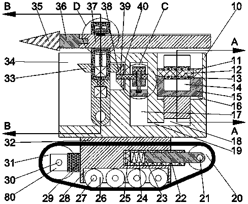
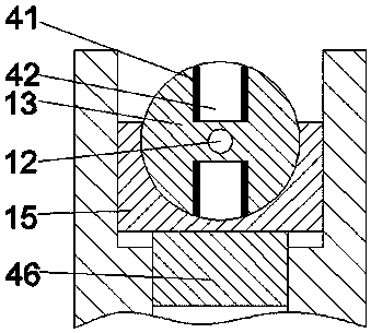
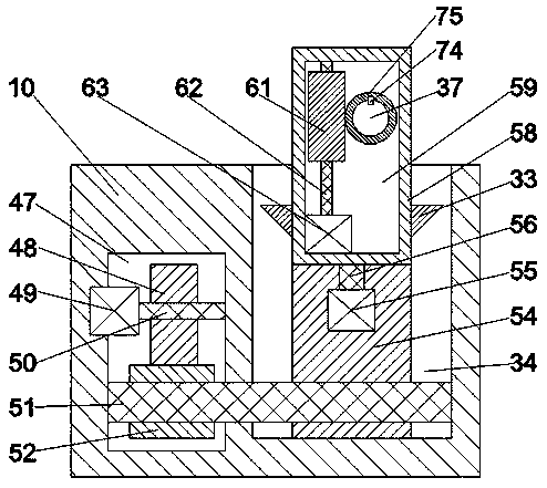
[0017] like Figure 1-Figure 5As shown, a hole distance measuring instrument of the present invention includes a main body 10, a chassis 32 extending downward is fixed on the bottom end surface of the main body 10, and a retractable opening is provided on the left end surface of the main body 10. Groove 34, the top end surface of the main body 10 is provided with a lifting chute 16, and the end wall on the right side of the receiving groove 34 is provided with a bevel gear chamber 40, and the main body located on the right side of the bevel gear chamber 40 10 is provided with a first hydraulic chamber 17 extending downward, and a hydraulic pipeline 19 extending left and right is fixed in the main body 10 below the first hydraulic chamber 17, and the left extension end of the hydraulic pipeline 19 is It communicates with the extension end of the bottom of the first hydraulic chamber 17, and a second hydraulic chamber 18 extending downward is opened on the bottom end wall of the...


PUM


Abstract

The invention discloses a hole spacing measuring instrument. The instrument comprises a main body. A chassis extending downwards is fixedly arranged on the bottom end surface of the main body. A storage groove is formed in the left side end surface of the main body. A lifting sliding groove is formed in the top end surface of the main body. A bevel gear cavity is formed in the right side end wallof the storage groove. A first hydraulic cavity extending downwards is formed in the portion, located at the right side of the bevel gear cavity, of the main body. A hydraulic pipeline extending leftand right is fixedly arranged in the portion, located under the first hydraulic cavity, of the main body. The left side extending tail end of the hydraulic pipeline communicates with the bottom extending tail end of the first hydraulic cavity. A second hydraulic cavity extending downwards is formed in the bottom end wall of the lifting sliding groove. The bottom extending tail end of the second hydraulic cavity communicates with the right side extending tail end of the hydraulic pipeline.

Description

technical field [0001] The invention relates to the field of bridge construction, in particular to a hole distance measuring instrument. Background technique [0002] With the development of science and technology and the progress of society, the country has been promoting the development of high technology. In the field of bridge construction, there has always been a relatively difficult technical problem, that is, how to control the position of the drill hole during bridge drilling construction, and how to accurately control the bridge drilling. The depth, size and angle of the drilled hole during construction, many existing equipment can only simply drill downwards, and cannot control the depth, size and angle of the drilled hole, so there is an urgent need for a device solve such problems. Contents of the invention [0003] The technical problem to be solved by the present invention is to provide a hole distance measuring instrument, which can solve the above-mentione...

Claims


Application Information

Patent Timeline
Patent Type & Authority Applications(China)
IPC IPC(8): E21B7/02E21B15/00E21B19/18
CPCE21B7/02E21B15/003E21B19/18
Inventor 吴莉
Owner 吉春雷
Why Eureka
Try Eureka