


Quick Research
Generate reliable direction feasibility study reports for your R&D in just a few steps.

Technical Q&A
Discover and master advanced knowledge NOW. Basics, ideas, possibilities, all at once.

Find Solutions
As an expert in R&D theories, this can generate solutions to your technical problems instantly.

Evaluate Feasibility
Analyze your overall solution with one click, know your potential R&D risks in advance.

Monitor Landscape
Get weekly tech updates, stay abreast of the latest tech innovations and key insights.
Petroleum pipeline and welding equipment and welding method for petroleum pipeline
A technology for welding equipment and oil pipelines, applied in the field of oil pipelines, can solve the problems of reduced pipe thickness, weak welding, low efficiency, etc., and achieve the effects of improving fluidity, reducing overall hot-melting time, and facilitating welding
- Summary
- Abstract
- Description
- Claims
- Application Information
AI Technical Summary
Problems solved by technology
Method used
Image

Examples
Embodiment 1
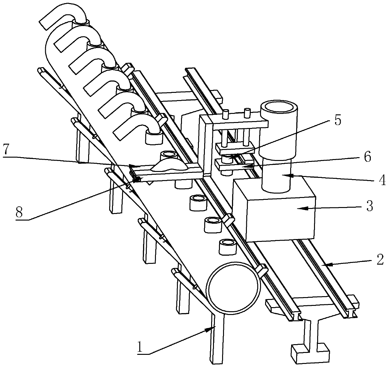
[0028]The main pipe does not move, and the welding device moves horizontally relative to the main pipe. A transmission mechanism is provided on the base 3. The transmission mechanism includes a servo motor, a transmission rod, a hub and a third bevel gear. The third bevel gear is sleeved on the transmission shaft. The hub is provided with two One is respectively installed on the two ends of the transmission rod, and rolls on the guide rail, the output shaft of the servo motor is connected with the fourth bevel gear, and the third gear meshes with the fourth bevel gear. The rotation of the driver motor is transmitted to the wheel hub through the transmission rod, so that the wheel hub rolls on the track 2, driving the clamping mechanism and the hot-melt mechanism to move horizontally, which is simple and convenient, and the transmission is accurate and stable. Adding spacers between them can adjust the balance of the track 2.
Embodiment 2
[0030] The welding mechanism does not move, and the main pipe moves horizontally relative to the welding device. Rollers are provided on the inner sides of the two branches of the bracket 1 used to support the main pipe to reduce the friction between the main pipe and the bracket 1, facilitate the movement of the main pipe and avoid scratching of the bracket 1 Injure the supervisor, set a power mechanism at one end of the supervisor to move it, it includes the first shaft, the second shaft, a gear box and a stepping motor, the first shaft and the second shaft are arranged in parallel, and are not located on the upper and lower sides of the supervisor One end of the first rotating shaft is coaxially fixedly connected with a driven wheel, one end of the second rotating shaft is coaxially fixedly connected with a driving wheel, the driving wheel and the driven wheel are driven by a belt, and the main shaft of the stepping motor and the input shaft of the gearbox are connected throu...
Embodiment 3
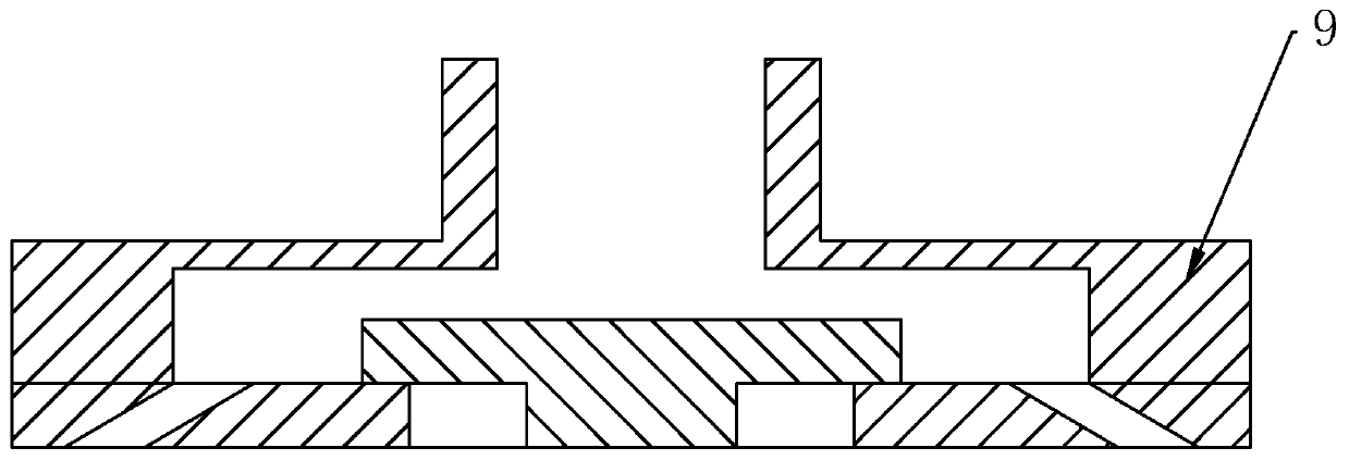
[0037] The rotating assembly includes a cylinder, a chain, a gear and an extension spring. The cylinder is connected to the fixed plate 6, the piston rod of the cylinder is fixedly connected to one end of the chain, the other end of the chain is fixedly connected to the extension spring, and the other end of the extension spring is connected to the fixed plate 6. To connect, the gear is sleeved outside the hot-melt pipe 5 and meshed with the chain, and the hot-melt pipe 5 is turned forward and backward through the cooperation of the cylinder and the tension spring.
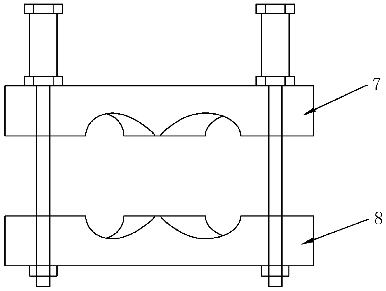
[0038] A welding method, the left splint 7 does not move, the right splint 8 is separated from the left splint 7, after the auxiliary pipe is installed in the clamping hole, the left splint 7 and the right splint 8 are spliced and fixed; the hot-melt mechanism moves to the top of the connecting pipe, Put the bottom end of the hot-melt pipe 5 in the connecting pipe for 2s~5s, move the clamping mechanism down and s...
PUM
 Abstract
Description
Claims
Application Information
 - R&D Engineer
- R&D Manager
- IP Professional
- Industry Leading Data Capabilities
- Powerful AI technology
- Patent DNA Extraction
Browse by: Latest US Patents, China's latest patents, Technical Efficacy Thesaurus, Application Domain, Technology Topic, Popular Technical Reports.
© 2024 PatSnap. All rights reserved.Legal|Privacy policy|Modern Slavery Act Transparency Statement|Sitemap|About US| Contact US: help@patsnap.com