Material crushing and grinding machine and using method thereof

A grinding machine and material technology, applied in the grinding machine field, can solve the problems of reducing the impact force and reducing the service life of the grinding chamber, so as to achieve the effects of prolonging the service life, increasing the grinding rate and avoiding damage

Active Publication Date: 2020-12-11
BOYEE SHENZHEN IND TECH CO LTD
View PDF6 Cites 0 Cited by
  • Summary
  • Abstract
  • Description
  • Claims
  • Application Information

AI Technical Summary

Problems solved by technology

[0005] The present invention can solve the problem that materials of different volumes will be mixed together to form a material layer during grinding. During grinding, materials with larger volumes may be buried in a deeper position. The finely crushed material has the effect of reducing the impact force on the falling grinding body. It is difficult for the grinding body to substantially crush the buried material. The grinding body has a certain weight and may smash the surface of the grinding chamber into a depression when it falls. , reducing the service life of the grinding chamber and other problems

Method used


Image

  • Material crushing and grinding machine and using method thereof
  • Material crushing and grinding machine and using method thereof
  • Material crushing and grinding machine and using method thereof

Examples


Embodiment Construction

[0034] Embodiments of the present invention will be described below with reference to the drawings. In the process, in order to ensure the clarity and convenience of illustration, we may exaggerate the width of the lines or the size of the constituent elements in the diagram.

[0035] In addition, the following terms are defined based on the functions in the present invention, and may be different according to the user's or operator's intention or practice. Therefore, these terms are defined based on the entire content of this specification.

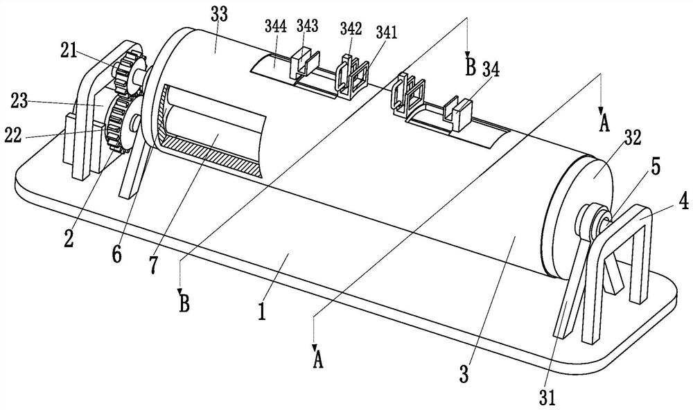
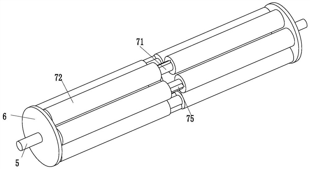
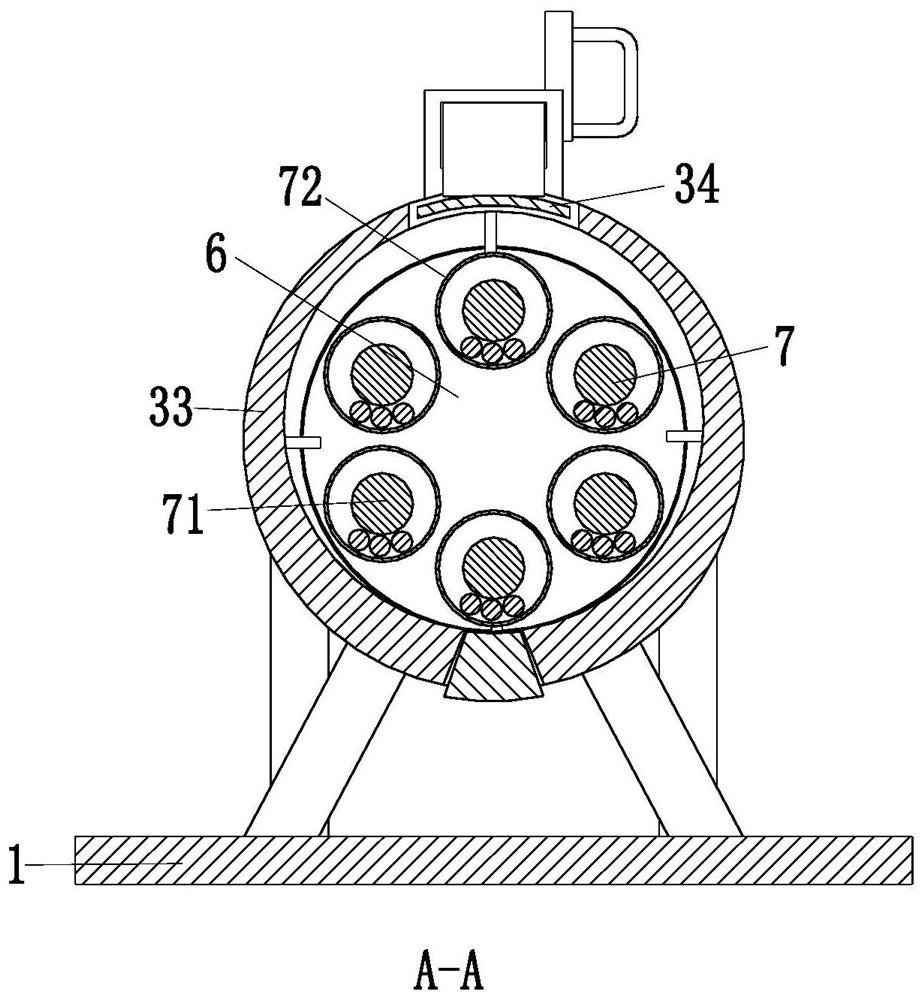
[0036] Such as Figure 1 to Figure 5 As shown, a material crushing and grinding machine includes a bottom plate 1, a variable speed drive module 2, a fixed outer tube 3, two U-shaped frames 4, two rotating shafts 5, two circular plates 6 and a built-in grinding roller 7, the described The upper end of the bottom plate 1 is equipped with a fixed outer tube 3, and the left and right ends of the fixed outer tube 3 are equipped with two ro...


PUM


Abstract

The invention relates to a material crushing and grinding machine and a using method thereof. The material crushing and grinding machine comprises a bottom plate, a speed change driving module, a fixed outer pipe, two U-shaped frames, two rotating shafts, two circular plates and a built-in grinding roller, wherein the fixed outer pipe is arranged at the upper end of the bottom plate, the left endand the right end of the fixed outer pipe are provided with the two rotating shafts through bearings, the inner ends of the rotating shafts are installed on the circular plates, the outer ends of therotating shafts are arranged on the U-shaped frames through bearings, the U-shaped frames are arranged on the bottom plate, the built-in grinding roller is uniformly installed between the two round plates through a pin shaft, and a speed change driving module is arranged at the left end of the bottom plate. According to the material crushing and grinding machine, in the existing grinding process,materials with different volumes can be mixed together to form a material layer, and during grinding, the materials with a large volume can be buried in a deeper position, a grinding body falls into the crushing process, the crushed materials on the upper surface of the material layer plays a role in relieving impact force on the falling grinding body, the grinding body has the weight, and the problem that the surface of a grinding cavity can be knocked out of the grinding cavity during falling can be solved.

Description

technical field [0001] The invention relates to the field of grinders, in particular to a material crushing grinder and a use method thereof. Background technique [0002] Grinder is a kind of equipment for crushing materials. Due to its high crushing rate, it is usually used in the production industries such as cement, refractory materials, fertilizers, black and non-ferrous metals, and glass ceramics. The existing grinder usually puts materials into In the grinding chamber, the material is crushed by the grinding body, but the following problems will occur during the grinding process: [0003] 1. Materials of different volumes will be mixed together to form a material layer. When grinding, larger materials may be buried in a deeper position. During the process of falling and crushing the grinding body, the finely divided materials on the upper surface of the material layer will affect the falling grinding body. It has the effect of reducing the impact force, and it is dif...

Claims


Application Information

Patent Timeline
Patent Type & Authority Patents(China)
IPC IPC(8): B02C4/02B02C4/28
CPCB02C4/02B02C4/28
Inventor 郭庆庆何海峰何欣悦
Owner BOYEE SHENZHEN IND TECH CO LTD
Why Eureka
Try Eureka