
Motion intention recognition device for lower extremity exoskeletons and method thereof

A technology for motion intentions and recognition devices, applied in applications, medical science, manipulators, etc., can solve problems such as increased cost, large size, and complex recognition models

Active Publication Date: 2019-08-20
NORTHEASTERN UNIV
View PDF9 Cites 44 Cited by
  • Summary
  • Abstract
  • Description
  • Claims
  • Application Information

AI Technical Summary

Problems solved by technology

At present, there are three main methods of motion intention recognition applied to lower extremity exoskeleton robots: 1. Gait phase recognition based on plantar pressure. The use of compliant control algorithms cannot recognize different road conditions and different sports actions; 2. Sports intention recognition based on surface electromyography signals (sEMG). There is too much motion information inside, and the current technology mainly focuses on muscle activation, and the recognition model is relatively complicated; 3. Human motion intention recognition based on force sensors, which detect the interaction force between the human body and the exoskeleton through the force sensor, and compare the interaction force according to the magnitude of the interaction force The recognition effect of human motion intention is better, but the multi-dimensional force sensor is expensive and bulky, so it needs to be fixed on the exoskeleton robot, which increases the cost

Method used


Image

  • Motion intention recognition device for lower extremity exoskeletons and method thereof
  • Motion intention recognition device for lower extremity exoskeletons and method thereof
  • Motion intention recognition device for lower extremity exoskeletons and method thereof

Examples


Embodiment Construction

[0079] The specific implementation manners of the present invention will be further described in detail below in conjunction with the accompanying drawings and embodiments. The following examples are used to illustrate the present invention, but are not intended to limit the scope of the present invention.

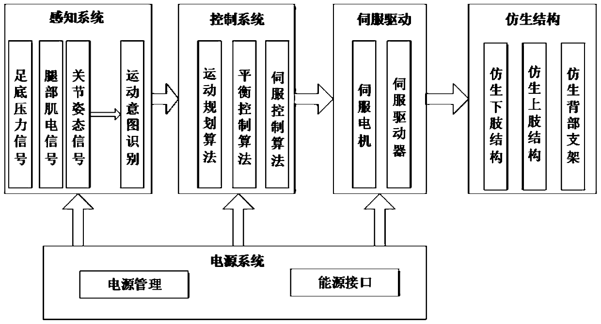
[0080] Lower limb assist exoskeleton system such as figure 1 As shown, it includes exoskeleton bionic mechanism system, perception system, control system, power supply system and drive system. Among them, the bionic mechanism system includes the bionic lower limb structure, the bionic upper limb structure, and the bionic back support; the perception system includes the acquisition of plantar pressure signals, leg myoelectric signals, joint posture signals, and movement intention recognition; the control system includes motion planning algorithms, balance Control algorithm, servo control algorithm; power system includes power management system and energy interface; servo ...


PUM


Abstract

The invention discloses a motion intention recognition device for lower extremity exoskeletons and a method thereof, and belongs to the technical field of lower extremity exoskeleton robots. The motion intention recognition device comprises a lower extremity EMG signal acquisition module, a plantar pressure acquisition module, a lower extremity inertial information measurement module, a data acquisition and transmission module and a central controller. An offline database gait trajectory based on the plantar pressure signal is obtained by using one-against-one SVM multi-classification and a real-time prediction trajectory of joint angle based on EMG signal is obtained by using CNN online joint angle estimation model. In addition, the variable gain information of the two trajectories is fused according to the fatigue degree of muscles to provide an accurate motion expectation trajectory for the lower extremity joint actuation of the exoskeleton robot. The invention effectively combinesthe advancement of the EMG signal and the stability of the plantar pressure signal, greatly improves the accuracy and real-time capability of the motion intention recognition, and provides sufficientassurance for the safety and the power assisting efficiency of the exoskeleton robot.

Description

technical field [0001] The invention belongs to the technical field of lower limb exoskeleton robot perception, and in particular relates to a device and method for recognizing motion intentions of a lower limb exoskeleton robot. Background technique [0002] With the rapid development of modern science and technology, the level of weapons and equipment has increasingly become an important guarantee for the victory of modern warfare, and the status of individual combat exoskeletons in military struggles has gradually increased. At the same time, the problem of aging in modern society is becoming more and more serious. Inconvenience in legs and feet is one of the serious problems in the lives of the elderly. Light-weight walking exoskeletons are of great significance to improving the quality of life of the elderly. [0003] As a typical human-machine collaborative robot, exoskeleton robots can accurately and quickly recognize human motion intentions. Figure 1 has been a majo...

Claims


Application Information

Patent Timeline
IPC IPC(8): A61B5/103A61B5/11A61B5/00A61B5/0488B25J9/00
CPCA61B5/1038A61B5/1118A61B5/6807A61B5/7203A61B5/7235A61B5/725A61B5/7253A61B5/7267A61B5/389B25J9/0006
Inventor 蒋超超王斐秦皞
Owner NORTHEASTERN UNIV
Learn More