
Tinning and detecting device for relay terminal

A technology for testing equipment and relays, applied in relays, circuits, electrical components, etc., can solve the problems of greatly affecting the number of personnel, wasting time, and unable to improve production efficiency

Active Publication Date: 2019-08-16
诸暨市科讯电子科技有限公司
View PDF4 Cites 1 Cited by
  • Summary
  • Abstract
  • Description
  • Claims
  • Application Information

AI Technical Summary

Problems solved by technology

Under normal circumstances, the release voltage of the relay is about 10-50% of the pull-in voltage. If the release voltage is too low, it cannot be used normally, which will pose a threat to the stability of the circuit and make the work unreliable.
[0005] Manual tinning is basically used for existing relay terminals. Manual tinning has low work efficiency and mediocre tinning effect. Manual tinning has high requirements for operators and requires a large number of technicians. When manpower is insufficient, the production level will drop. There are some equipment that can automatically tin the relay terminals. When in use, workers can operate the equipment to tin the relay terminals, but the tinned relay terminals need to be removed manually, which takes time Waste, which affects production efficiency. It is usually impossible to detect whether the product is good or bad for tinned relay terminals, and manual inspection is required. The number of personnel has a great impact, so it is necessary to design a method that can automatically tin the relay terminals, and at the same time automatically remove the tinned relay terminals, and perform automatic quality inspection on the tinned terminals, and detect different problems. The relay terminals are classified and automatically sent to the repaired relay terminals for tinning and testing equipment

Method used


Image

  • Tinning and detecting device for relay terminal
  • Tinning and detecting device for relay terminal
  • Tinning and detecting device for relay terminal

Examples


Embodiment Construction

[0033] The technical solutions of the present invention will be further described below in conjunction with the drawings and specific implementations.

[0034] Among them, the drawings are only used for exemplary description, and they are only schematic diagrams rather than physical drawings, and cannot be understood as a limitation of the patent; in order to better illustrate the embodiments of the present invention, some parts of the drawings may be omitted, Enlargement or reduction does not represent the size of the actual product; for those skilled in the art, it is understandable that some well-known structures in the drawings and their descriptions may be omitted.

[0035] The same or similar reference numbers in the drawings of the embodiments of the present invention correspond to the same or similar components; in the description of the present invention, it should be understood that if the terms "upper", "lower", "left", "right" appear , "内", "外", etc. indicate the orient...


PUM


Abstract

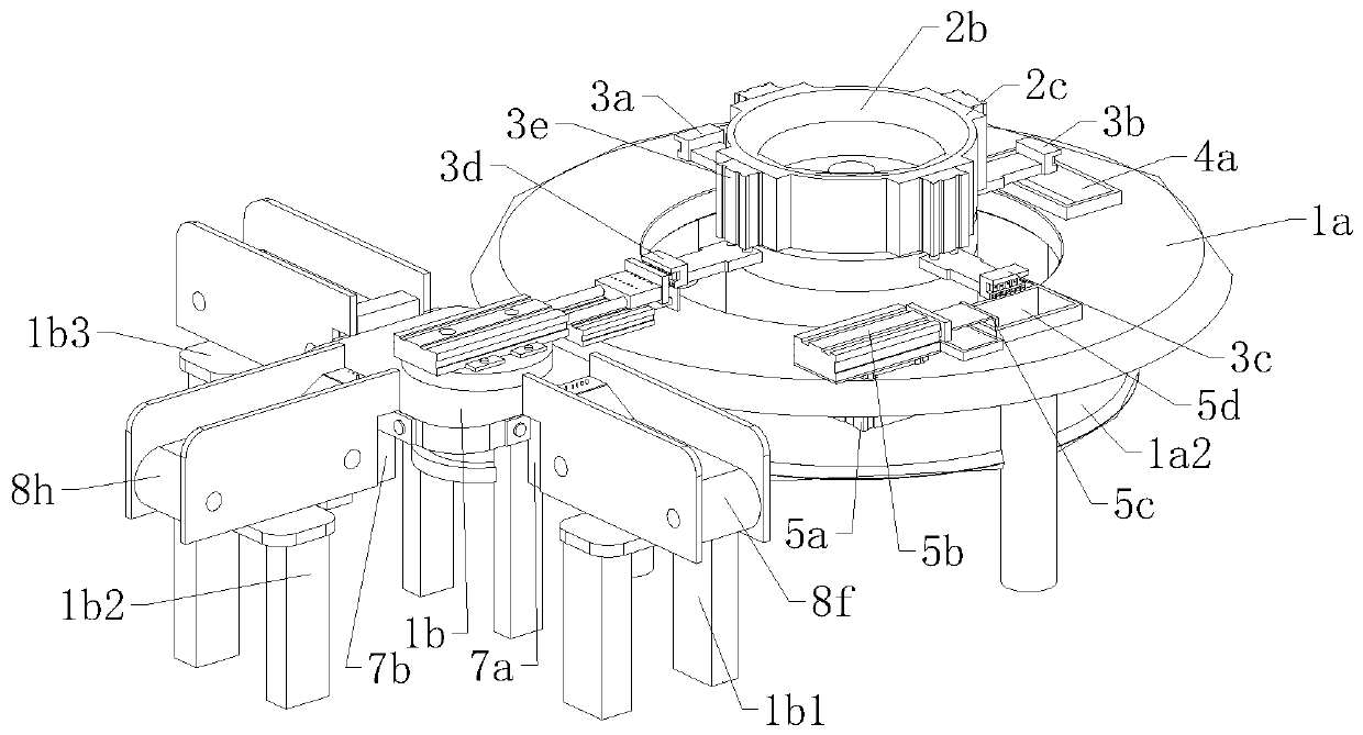
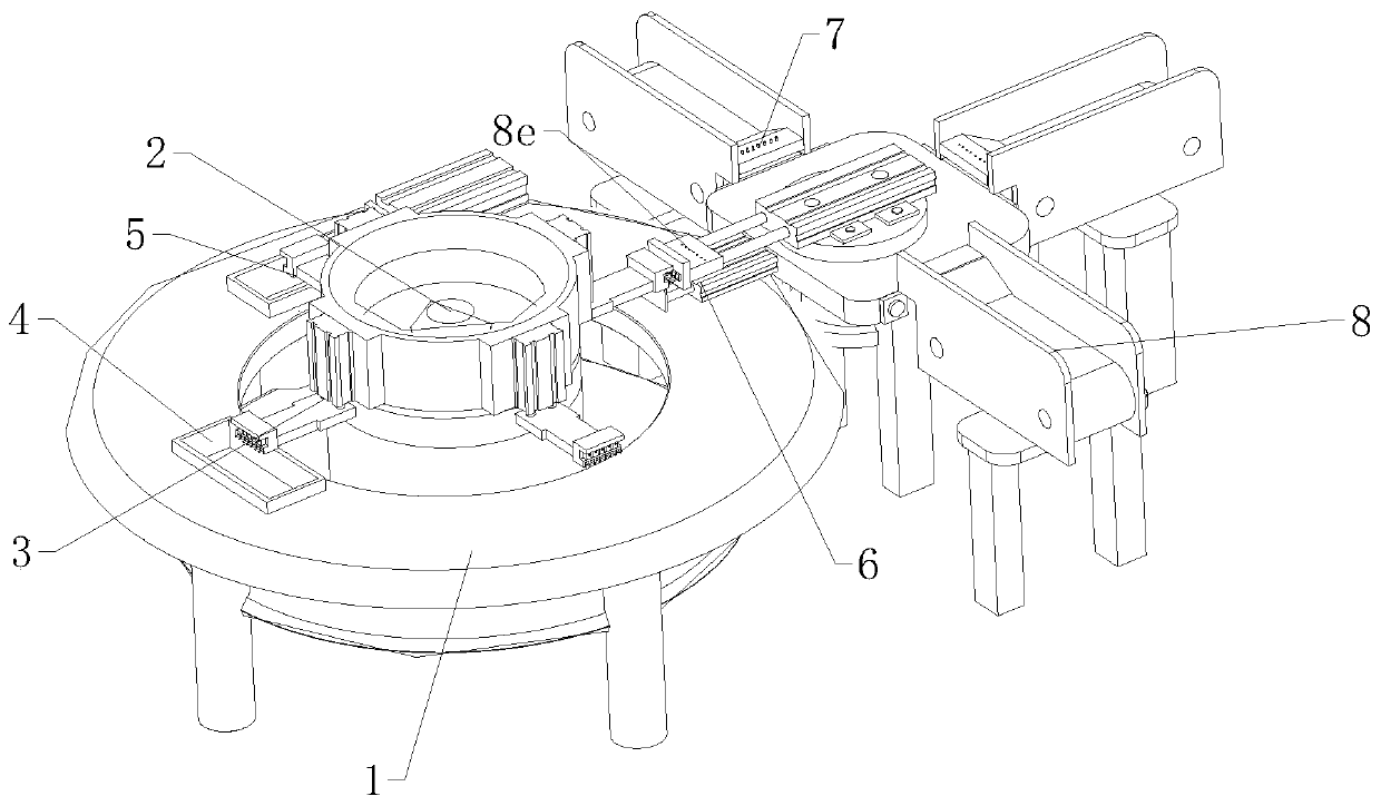
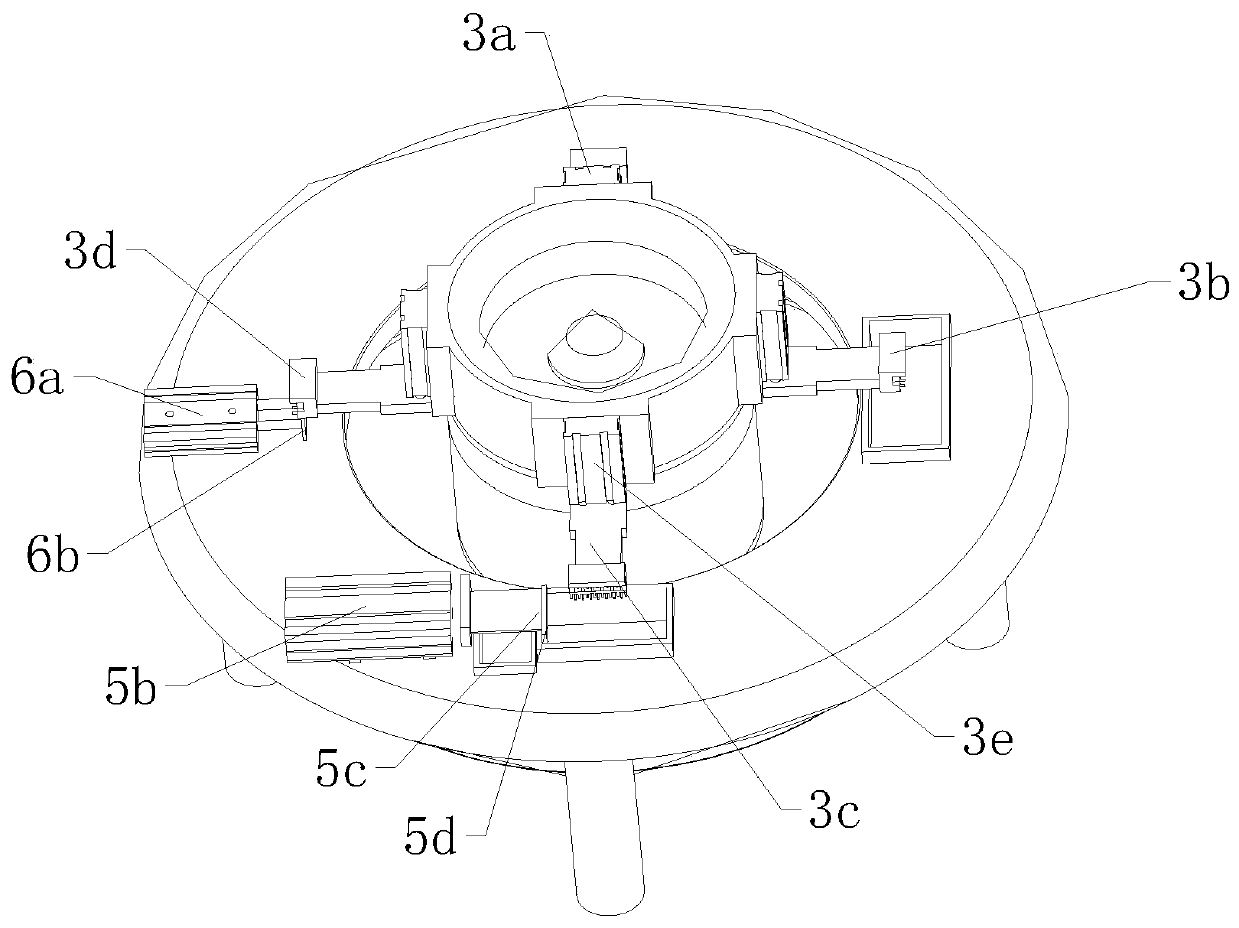
The invention relates to the field of relay terminal production equipment and particularly relates to a tinning and detecting device for a relay terminal. The device comprises a supporting mechanism,a rotating mechanism, a fixed mechanism, a welding aiding mechanism, a tinning mechanism, a discharging mechanism, a detecting mechanism and a sorting mechanism. The supporting mechanism is verticallyarranged, the tinning mechanism is fixedly connected to the supporting mechanism, the discharging mechanism is fixedly connected to the supporting mechanism, and the detecting mechanism is fixedly connected to a side wall of the supporting mechanism. The tinning mechanism comprises a first cylinder, a second cylinder, a tin scraping block and a tin liquid pool. The detecting mechanism comprises athird cylinder, a fourth cylinder, a first detecting head and a second detecting head. According to the tinning and detecting device for the relay terminal, the automatic tinning of the relay terminal is carried out, at the same time, the relay terminal is automatically taken down, the relay terminal is detected, relay terminals of different problems are classified, the workflow is simplified, the work and production efficiency are improved, the relay terminal is convenient to tin and detect, the dependence on persons is reduced, and the automatic integrated production is achieved.

Description

Technical field [0001] The invention relates to the field of relay terminal production equipment, in particular to a relay terminal tinning and detection equipment. Background technique [0002] A relay is an electrical control device. It is an electrical appliance that causes the controlled quantity to undergo a predetermined step change in the electrical output circuit when the input quantity changes meet the specified requirements. It has a connection between the control system and the controlled system. The interaction relationship is usually used in automated control circuits. It is actually an "automatic switch" that uses a small current to control the operation of a large current, so it plays the role of automatic adjustment, safety protection, and conversion circuit in the circuit. [0003] Electromagnetic relays are generally composed of iron cores, coils, armatures, contact reeds, etc. As long as a certain voltage is applied to both ends of the coil, a certain current wil...

Claims


Application Information

Patent Timeline
IPC IPC(8): H01H49/00G01R31/12
CPCG01R31/12H01H49/00
Inventor 陈巧巧
Owner 诸暨市科讯电子科技有限公司
Learn More