
Backlight module and display device

A technology of backlight module and light source, which is applied in optics, nonlinear optics, instruments, etc., and can solve problems such as poor lattice pattern on the display screen

Inactive Publication Date: 2019-08-16
XIAMEN TIANMA MICRO ELECTRONICS
View PDF5 Cites 2 Cited by
  • Summary
  • Abstract
  • Description
  • Claims
  • Application Information

AI Technical Summary

Problems solved by technology

[0004] The embodiment of the present invention provides a backlight module and a display device, which are used to solve the problem in the prior art that the display screen has poor grid pattern due to the blocking of the barrier wall.

Method used


Image

  • Backlight module and display device
  • Backlight module and display device
  • Backlight module and display device

Examples


Embodiment Construction

[0032] Aiming at the problem in the prior art that the grid pattern on the display screen is bad due to the blocking of the partition wall, the embodiment of the present invention provides a backlight module and a display device.

[0033] The specific implementation manners of the backlight module and the display device provided by the embodiments of the present invention will be described in detail below with reference to the accompanying drawings. The thickness and shape of each film layer in the drawings do not reflect the real scale, and the purpose is only to illustrate the content of the present invention.

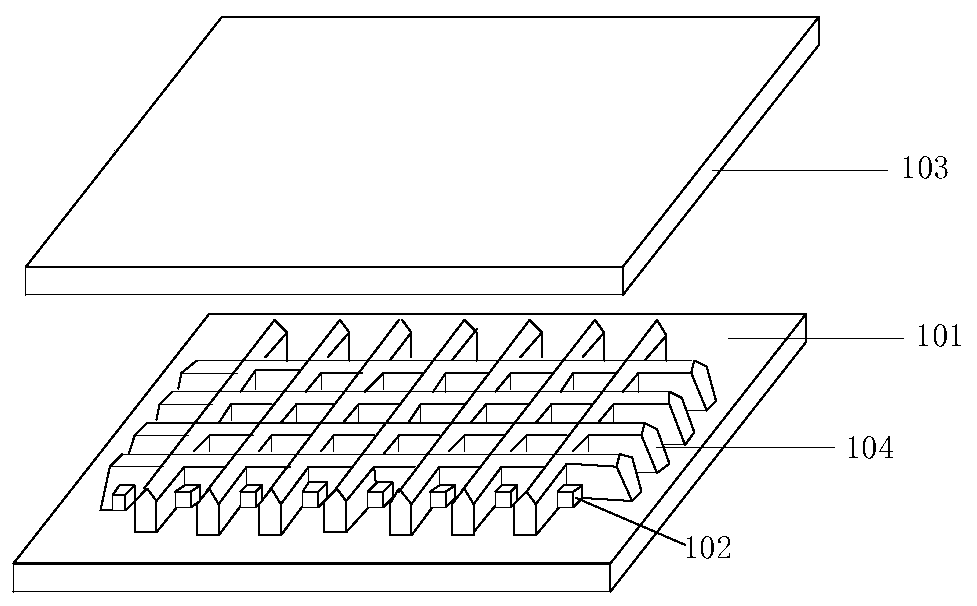
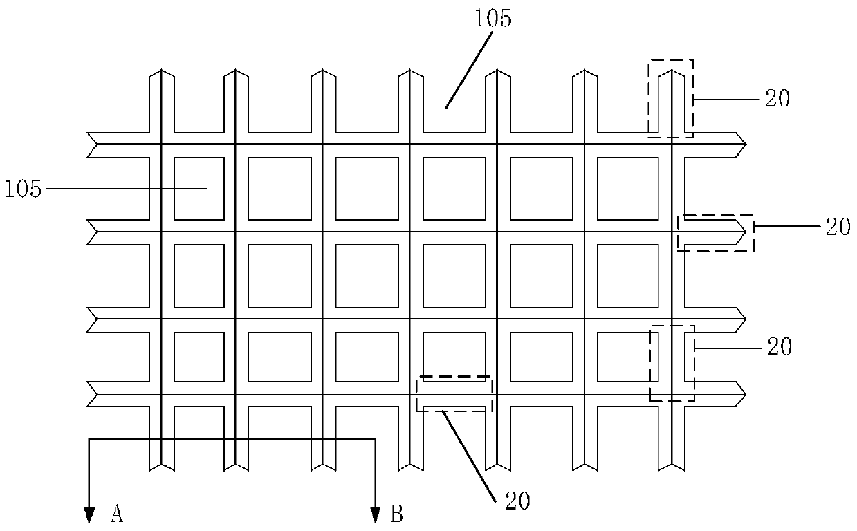
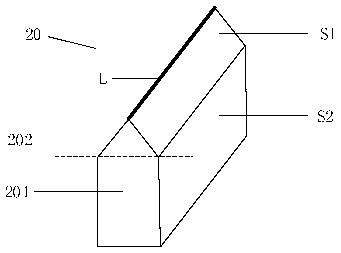
[0034] figure 1 is a schematic diagram of a three-dimensional structure of a backlight module in an embodiment of the present invention, figure 2 It is a schematic diagram of the top view structure of the barrier layer in the embodiment of the present invention, image 3 It is a schematic structural diagram of a barrier wall in an embodiment of the present inventi...


PUM


Abstract

The invention discloses a backlight module and a display device. The backlight module comprises a baseplate; multiple light sources on the baseplate; an optical film layer located at one side, far away from the baseplate, of each light source; and a barrier layer supported between the baseplate and the optical film layer; the barrier layer separates multiple light sources on the baseplate into multiple light-emitting regions, and each light-emitting region comprises at least one light source; the barrier layer comprises multiple barrier walls located between adjacent light-emitting regions; the barrier walls comprise a first barrier wall, and a second barrier wall located between the first barrier wall and the optical film layer; the second barrier wall has a tip contacting with the optical film layer in any section vertical to an intersecting line between adjacent light-emitting regions; and a side surface of the first barrier wall and the side surface of the second barrier wall at the same side are not in the same plane at one side of the barrier wall. The backlight module can relieve the problem that the lattice pattern is bad, and can effectively block the light-path crosstalking between the adjacent light-emitting regions.

Description

technical field [0001] The invention relates to the field of display technology, in particular to a backlight module and a display device. Background technique [0002] In recent years, as high-dynamic range (High-Dynamic Range, HDR) technology is more and more applied to fields such as digital photography, movie art, and television. If the HDR technology is applied to a liquid crystal display, the liquid crystal display needs to meet special technical requirements, specifically, the liquid crystal display should be able to realize block control. Since the partitions of the light sources in the direct-lit backlight module correspond to the partitions of the liquid crystal display panel, the better the effect of local dimming, the higher the dynamic contrast of the picture and the better the display effect. [0003] In the prior art, in order to overcome the problem of ring-shaped light caused by partial light sources lighting up and penetrating into adjacent areas, barrier ...

Claims


Application Information

Patent Timeline
IPC IPC(8): G02F1/13357
CPCG02F1/133602
Inventor 卢丽君李凯李静邱英彰
Owner XIAMEN TIANMA MICRO ELECTRONICS
Learn More