
Rock complex resistivity signal measurement device, structure and method

A complex resistivity and signal measurement technology, applied in the field of geotechnical engineering, can solve the problems of low reuse rate of the overall device, poor portability, and inability to ensure effective contact between the measuring electrode and the sample, and achieves improved test efficiency, convenient measurement, simple structure

Inactive Publication Date: 2019-08-16
SHANDONG UNIV
View PDF7 Cites 1 Cited by
  • Summary
  • Abstract
  • Description
  • Claims
  • Application Information

AI Technical Summary

Problems solved by technology

In terms of rock mass complex resistivity signal measurement, the effective contact between the measuring electrode and the measured sample can improve the signal-to-noise ratio of the measurement data, but the inventors found that the measuring electrodes currently on the market are not suitable for the measurement of rock mass resistivity signals, and cannot Ensure the effective contact between the measuring electrode and the sample, and the overall device has a low reusability rate, which can only be used in the laboratory, and has the problem of poor portability

Method used


Image

  • Rock complex resistivity signal measurement device, structure and method
  • Rock complex resistivity signal measurement device, structure and method
  • Rock complex resistivity signal measurement device, structure and method

Examples


Embodiment Construction

[0042] It should be noted that the following detailed description is exemplary and intended to provide further explanation of the present invention. Unless defined otherwise, all technical and scientific terms used herein have the same meaning as commonly understood by one of ordinary skill in the art to which this invention belongs.

[0043] It should be noted that the terminology used here is only for describing specific embodiments, and is not intended to limit exemplary embodiments according to the present invention. As used herein, unless the context clearly dictates otherwise, the singular is intended to include the plural, and it should also be understood that when the terms "comprising" and / or "comprising" are used in this specification, they mean There are features, steps, operations, means, components and / or combinations thereof.

[0044] As the introduction of the background technology, there are deficiencies in the prior art. In order to solve the above technical ...


PUM

PropertyMeasurementUnit
radiusaaaaaaaaaa
thicknessaaaaaaaaaa
radiusaaaaaaaaaa

Abstract

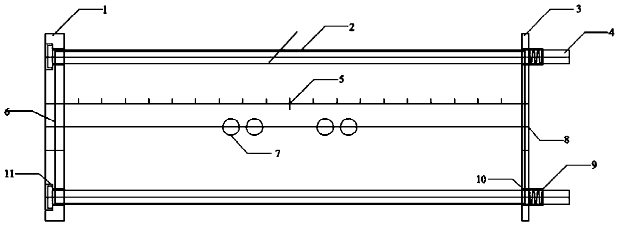
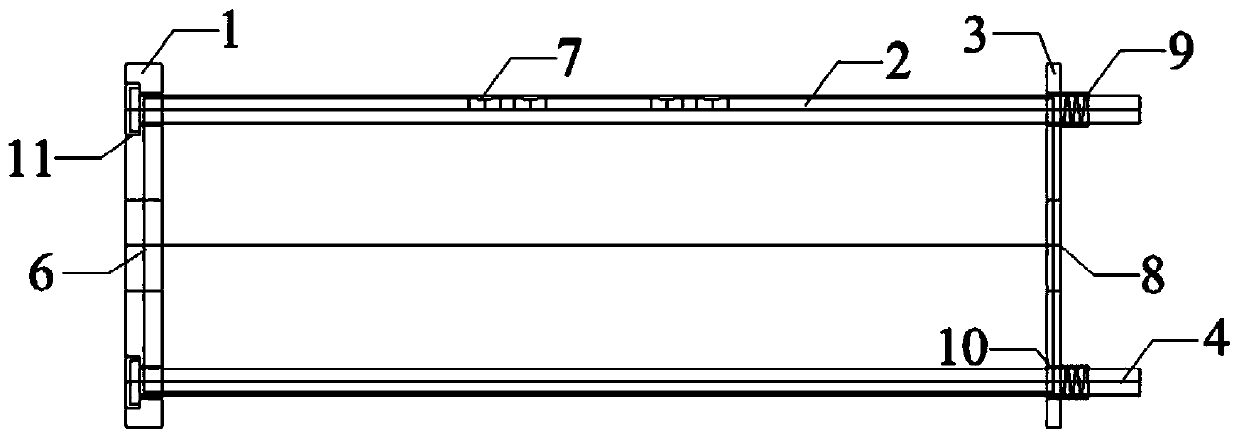
The invention discloses a rock complex resistivity signal measurement device, fabrication and application method. By the rock complex resistivity signal measurement device, the problems that a measurement electrode and a sample cannot be enabled to be effectively contacted and the device is relatively poor in portability. The rock complex resistivity signal measurement device has the beneficial effects that the rock complex resistivity signal measurement device is convenient to carry, and the experiment efficiency can be effectively improved. The rock complex resistivity signal measurement device comprises a detachable container and the measurement electrode, wherein an accommodating cavity is formed in the container and is used for placing a test sample, a power supply electrode is arranged in the accommodating cavity and can be in contact with the test sample, a measurement electrode hole is formed in the container and is used for installing the measurement electrode, the measurementelectrode can be contacted with the test ample in the accommodating cavity through the measurement hole, and the measurement electrode is not directly contacted with the test sample in the accommodating cavity while is indirectly contacted with the test sample by a salt bridge solution in the electrode. The rock complex resistivity signal measurement device aims to prevent the situation that a metal electrode generates an electrode polarization effect to affect a measurement signal.

Description

technical field [0001] The invention relates to the fields of geotechnical engineering, geophysics, and hydrogeology, and in particular relates to a rock mass complex resistivity signal measuring device, structure and method. Background technique [0002] At this stage, with the rapid development of social and economic construction, the continuous improvement of people's living standards in various countries, and the rapid growth of the world's water demand, the water storage capacity and anti-seepage capacity of reservoirs are particularly important. At present, many anti-seepage materials are used to block seepage in reservoirs, but it is difficult to judge which material can better achieve anti-seepage. At this stage, the post-evaluation methods for the anti-seepage effect of the reservoir are mainly methods such as sounding and cross-hole operation in the well. In order to achieve non-destructive evaluation, it is recommended to use complex resistance method, such as ex...

Claims


Application Information

Patent Timeline
Patent Type & Authority Applications(China)
IPC IPC(8): G01N15/08
CPCG01N15/08G01N15/0806
Inventor 毛德强李召峰胡开友张健宋瑞超赵瑞珏
Owner SHANDONG UNIV
Learn More