Intelligent detecting instrument for measuring optical cable and power cable insulating sheaths
A cable insulation and intelligent detection technology, which is applied in the direction of instruments, measuring devices, and optical devices, can solve problems such as discharge, safety accidents, and production profit decline, and achieve the effects of reasonable appearance design, convenient movement, and simple design structure
- Summary
- Abstract
- Description
- Claims
- Application Information
AI Technical Summary
Problems solved by technology
Method used
Image
Examples
Embodiment 1
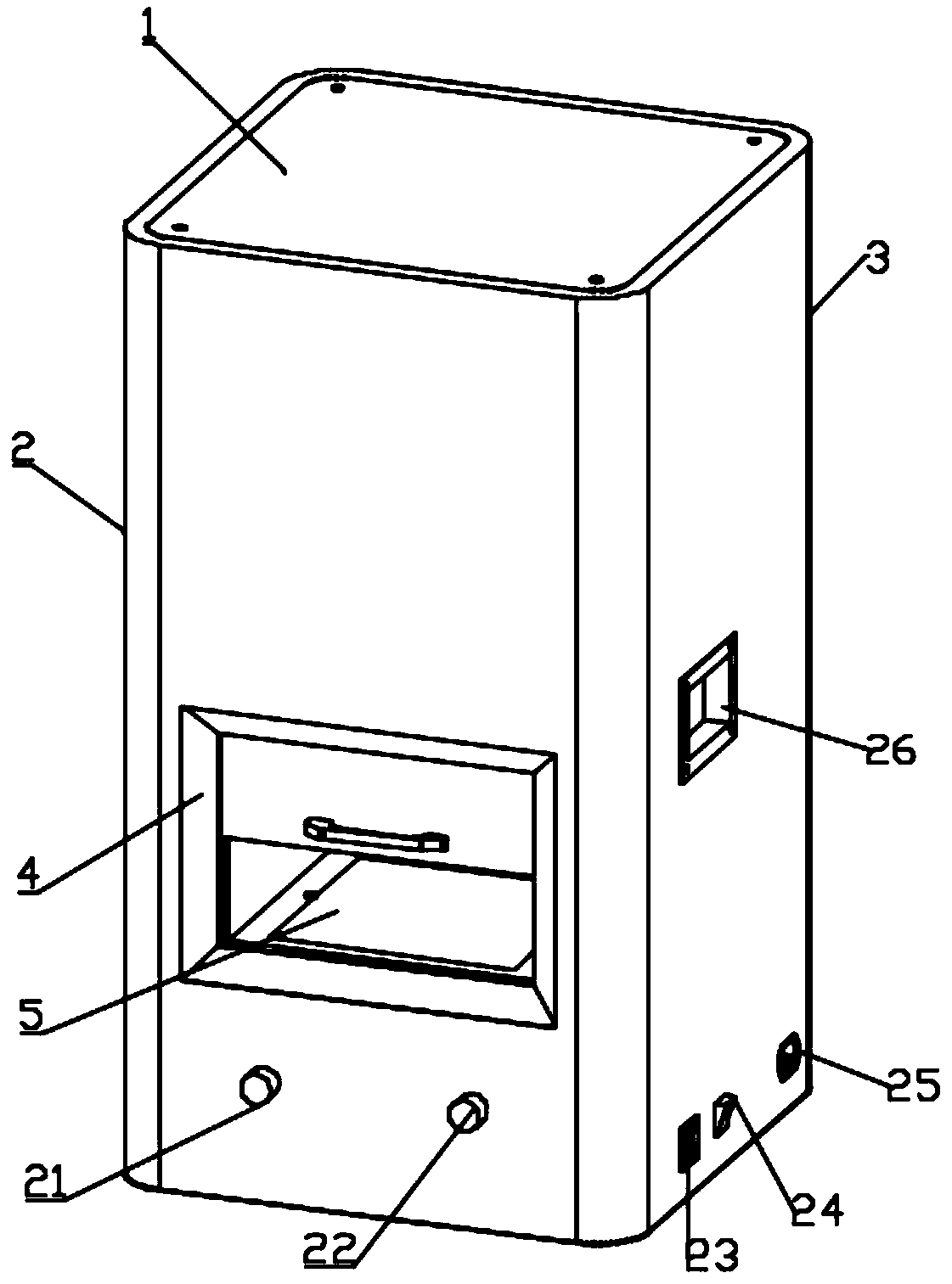
[0024] see figure 1 , In the embodiment of the present invention, an intelligent detection instrument for measuring optical cables and cable insulation sheaths, the upper and lower ends of the cabinet body 2 are symmetrically assembled with end covers 1 through riveting and other detachable connection methods. A backboard 3 is assembled on the side by riveting or other detachable connection methods, and a visual window 4 and a detection structure 6 are embedded in the cabinet 2 .
[0025] The cabinet body 2 is formed by bending a 1.2mm thick cold-rolled steel plate to form a "U"-shaped shell. The cabinet body 2 is formed into a front cabinet surface located on the front and side cabinet surfaces located on both sides. The back panel 3 It is connected to the back side edges of the side cabinet surfaces on both sides, and the connecting and connecting corners of the front cabinet surface and the side cabinet surfaces are arranged in an arc curved surface. Such a design can ensu...
Embodiment 2
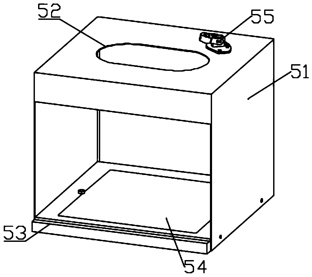
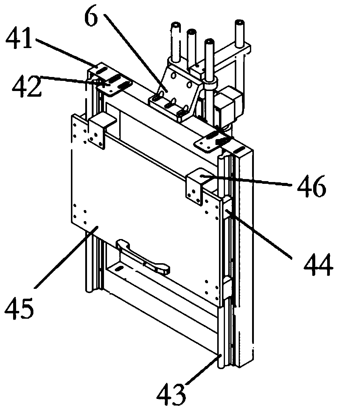
[0029] see Figures 2 to 4 , in the embodiment of the present invention, an intelligent detection instrument for measuring optical cables and cable insulation sheaths, on the basis of embodiment 1, the visual window 4 includes a frame embedded and fixed in the front cabinet surface of the cabinet body 2 41, the front side of the frame 41 is also provided with a sliding block structure, the upper end of the frame 41 is symmetrically provided with sliding rails 42 on both sides for cooperating with the sliding block structure to limit the position, and the lower surface of the sliding rail 42 is inlaid with permanent magnets piece.
[0030] The sliding block structure includes a slider 43 vertically fixed on both sides of the front of the frame 41, a baffle 44 slidably assembled on the slider 43, and a positioning piece 45 fixed on the front of the baffle 44. The positioning piece 45 has two upper ends. A mounting piece 46 is arranged symmetrically on the side. The mounting pie...
PUM
 Abstract
Description
Claims
Application Information
 - R&D Engineer
- R&D Manager
- IP Professional
- Industry Leading Data Capabilities
- Powerful AI technology
- Patent DNA Extraction
Browse by: Latest US Patents, China's latest patents, Technical Efficacy Thesaurus, Application Domain, Technology Topic, Popular Technical Reports.
© 2024 PatSnap. All rights reserved.Legal|Privacy policy|Modern Slavery Act Transparency Statement|Sitemap|About US| Contact US: help@patsnap.com


