
A new type of implanted relief well depressurization drainage system and method

A drainage system and relief well technology, applied in construction, infrastructure engineering, etc., can solve the problems of slow reaction speed, easy sand boiling and sand surge, regardless of reverse filtration effect, etc., and achieve small disturbance, rapid well completion and monitoring The effect of hazard development

Active Publication Date: 2019-12-27
CHANGJIANG RIVER SCI RES INST CHANGJIANG WATER RESOURCES COMMISSION
View PDF4 Cites 0 Cited by
  • Summary
  • Abstract
  • Description
  • Claims
  • Application Information

AI Technical Summary

Problems solved by technology

[0003] 1. The traditional pressure relief well adopts the method of drilling first and placing the well pipe to form the well. If the drilling hole breaks through the clay layer during the flood season, new dangers such as sand boiling and sand gushing are more likely to occur.
[0004] 2. The construction of traditional relief wells is complicated, and requires drilling, running pipes, backfilling anti-filter materials, backfilling clay, well cleaning, and new drainage ditches, etc., and the response to dangerous situations is slow
[0005] 3. Regardless of the reverse filtration effect, the stainless steel permeable flower tube is directly implanted. When the permeable tube penetrates the clay layer, the wall of the flower tube sticks to the clay to block the hole wall, which is not conducive to the discharge of pore water.
In the absence of flood conditions, the benefits of flood control cannot be exerted, resulting in waste of engineering construction and redundant management

Method used


Image

  • A new type of implanted relief well depressurization drainage system and method
  • A new type of implanted relief well depressurization drainage system and method
  • A new type of implanted relief well depressurization drainage system and method

Examples


Embodiment Construction

[0036] The technical solutions in the present invention will be clearly and completely described below in conjunction with the accompanying drawings in the present invention.

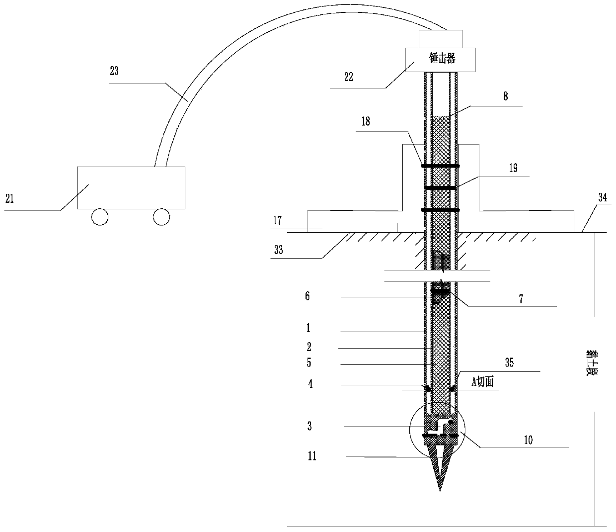
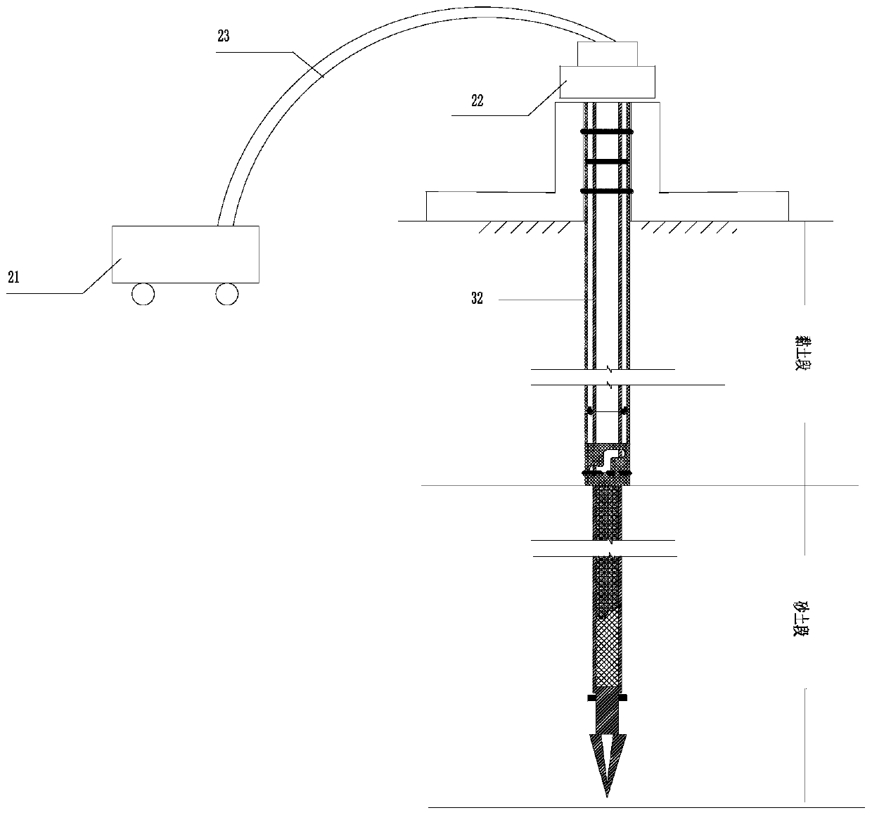
[0037] like figure 1 and figure 2 As shown, it is one embodiment of the new implanted relief well depressurization drainage system of the present invention, which is used for the management and monitoring of embankment piping hazards, including double-layer relief well pipe devices, relief well pipe installation devices, reverse filtration drainage device, internal and external well pipe rotary separation device, hammer implantation power device.

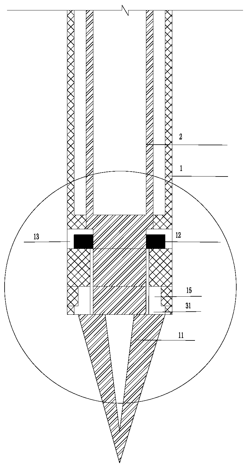
[0038] The double-layer decompression well pipe device allows the pressurized water in the foundation soil in the embankment to enter the decompression well, including the outer well pipe 1 and the inner well pipe 2, the outer well pipe 1 is a solid stainless steel pipe, and the hole wall is impermeable; The well pipe 2 is a stainless steel water-permeable...


PUM


Abstract

The invention provides a novel implanted pressure relief well depressurization drainage system and method. The novel implanted pressure relief well depressurization drainage system comprises a double-layer depressurization well casing device, a reverse filtering drainage device, an internal and external well casing rotation separating device and a hammering implanting power device; the double-layer depressurization well casing device comprises an external well casing and an internal well casing which are arranged in a nested mode, the external well casing is a stainless steel solid steel tube,the internal well casing is a stainless steel permeable floral tube and is arranged in the external well casing, and the internal well casing is planted into a sand soil layer; an internal well casing rotating device is used for separating the internal well casing from the external well casing to form a soil breaking cone, and stress is changed from the external well casing to the internal well casing; and the hammering implanting power device is connected with the double-layer depressurization well casing device through a hammering head, and soil extruding implanting power is transmitted tothe double-layer depressurization well casing device continuously. The embankment foundation soil body water pressure is reduced through a pressure relief well depressurization drainage principle, andthe effects of governing the piping dangerous case in the flood period and monitoring development of the embankment dangerous case are achieved.

Description

technical field [0001] The invention relates to the technical field of embankment flood fighting and emergency rescue, in particular to a novel implanted depressurization well depressurization drainage system and method, which are especially suitable for emergency rescue in flood season piping dangers. Background technique [0002] Most embankment foundations in my country present a dual structure stratum with clay in the upper layer and coarse and fine sand in the lower layer, and the clay in the upper layer has relatively poor permeability, generally 10 -5 ~10 -7 cm / s, the underlying sand layer has strong permeability, generally 10 -2 ~10 -4 cm / s, when the groundwater is high, the formation tends to be under pressure. When the water level of the river on the upstream side rises sharply during the flood season, due to the strong permeability of the sand layer, the river water leaks into the embankment through the groundwater in the sand layer, and the pressurized water e...

Claims


Application Information

Patent Timeline
Patent Type & Authority Patents(China)
IPC IPC(8): E02D19/10
CPCE02D19/10
Inventor 邬爱清盛小涛吴庆华李少龙张伟饶锡保程永辉熊勇崔皓东严敏肖利丁金华王金龙陈劲松汪啸
Owner CHANGJIANG RIVER SCI RES INST CHANGJIANG WATER RESOURCES COMMISSION
Learn More