


Quick Research
Generate reliable direction feasibility study reports for your R&D in just a few steps.

Technical Q&A
Discover and master advanced knowledge NOW. Basics, ideas, possibilities, all at once.

Find Solutions
As an expert in R&D theories, this can generate solutions to your technical problems instantly.

Evaluate Feasibility
Analyze your overall solution with one click, know your potential R&D risks in advance.

Monitor Landscape
Get weekly tech updates, stay abreast of the latest tech innovations and key insights.
Liquid flow system of flow cytometer, air tightness detection method and flow cytometer
A flow cytometer and air tightness technology, which is applied in the field of flow cytometer, can solve the problems of poor clogging detection accuracy, poor instrument reliability, poor practicability of instruments, and poor maintenance of flow cytometer, and achieves simple and convenient operation and convenience. The effect of blockage removal maintenance and reliability improvement
- Summary
- Abstract
- Description
- Claims
- Application Information
AI Technical Summary
Problems solved by technology
Method used
Image

Examples
Embodiment 1
[0082] This embodiment provides a method for detecting air tightness of the liquid flow system 10 of a flow cytometer, which includes the following steps:
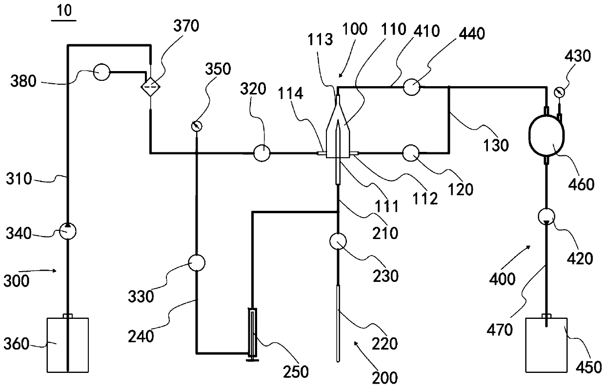
[0083] see figure 1 As shown, the liquid flow system 10 is in an initialized state to be tested;
[0084] Close the emptying valve 120, the filter exhaust valve 380, the sample control valve 230, the first sheath fluid control valve 320, the second sheath fluid control valve 330 and the negative pressure control valve 440; A certain volume of sheath fluid is pumped in or out to make the pressure reach 30 kPa, and the pressure value P2 of the sheath fluid pressure sensor 350 is read after 10 seconds. If |P2-P1|<0.5kPa, it means that the airtightness of the sheath liquid device 300 of the liquid flow system 10 is good, and if |P2-P1|≥0.5kPa, it means that the airtightness of the sheath liquid device 300 of the liquid flow system 10 is not good. it is good;
[0085] In the initialization state, read the pressure value P7 o...
Embodiment 2
[0089] This embodiment provides a method for detecting air tightness of the liquid flow system 10 of a flow cytometer, which is easy to operate, has high detection accuracy, and high detection efficiency.
[0090] The liquid flow system 10 air tightness detection method of the above-mentioned flow cytometer comprises the following steps:
[0091] see figure 1 As shown, the filter exhaust valve 380, the sample control valve 230, and the first sheath liquid control valve 320 of the liquid flow system 10 are opened, so that the sheath liquid device, the test device, and the sample loading device of the entire liquid circuit system are filled with sheath liquid. At this time, the liquid flow system 10 is in an initialized state to be tested;
[0092] Close the emptying valve 120, the sample control valve 230, the filter exhaust valve 380, the first sheath fluid control valve 320, the second sheath fluid control valve 330 and the negative pressure control valve 440;
[0093] Pump...
PUM
 Abstract
Description
Claims
Application Information
 - R&D Engineer
- R&D Manager
- IP Professional
- Industry Leading Data Capabilities
- Powerful AI technology
- Patent DNA Extraction
Browse by: Latest US Patents, China's latest patents, Technical Efficacy Thesaurus, Application Domain, Technology Topic, Popular Technical Reports.
© 2024 PatSnap. All rights reserved.Legal|Privacy policy|Modern Slavery Act Transparency Statement|Sitemap|About US| Contact US: help@patsnap.com