Combustor for gas stove

A technology for burners and gas stoves, which is applied in the direction of gas fuel burners, burners, and non-flammable liquid/gas transportation, etc. problem, to achieve the effect of increasing boundary conditions and combustion stability

Pending Publication Date: 2019-08-13
NINGBO FOTILE KITCHEN WARE CO LTD
View PDF1 Cites 8 Cited by
  • Summary
  • Abstract
  • Description
  • Claims
  • Application Information

AI Technical Summary

Problems solved by technology

[0002] The gas burner of the existing domestic gas cooker includes a gas mixing chamber, a first fire cover, an injection pipe, etc., wherein the gas mixing chamber of the burner is a very important part of the cooking range, and the function of the gas mixing chamber is to mix the gas so that the gas Mix with the primary air more evenly; at the same time supply the secondary air to the inner ring, the current one-piece fixed structure of the gas mixing chamber is not conducive to the cleaning of the cooker, especially the inside of the gas mixing chamber and the inside of the waist-shaped hole, the user is not easy to clean the gas mixing chamber There are also more and more complaints, such as the Chinese utility model patent "A Burner" with the patent number ZL201420072885 (the announcement number is CN2037314112U), or if the patent number is ZL200610052382.8 (the announcement number is CN1884911A) all disclose similar Such a mixed air chamber, in addition, supplies secondary air by supplying air from the waist-shaped hole of the air mixed chamber to the inner ring, but the reduction effect on the smoke of the inner ring is still very limited, and it is also necessary to adjust the air mixing chamber to the inner ring. The air supply effect is further improved

Method used


Image

  • Combustor for gas stove
  • Combustor for gas stove
  • Combustor for gas stove

Examples


Embodiment Construction

[0041] The present invention will be further described in detail below in conjunction with the accompanying drawings and embodiments.

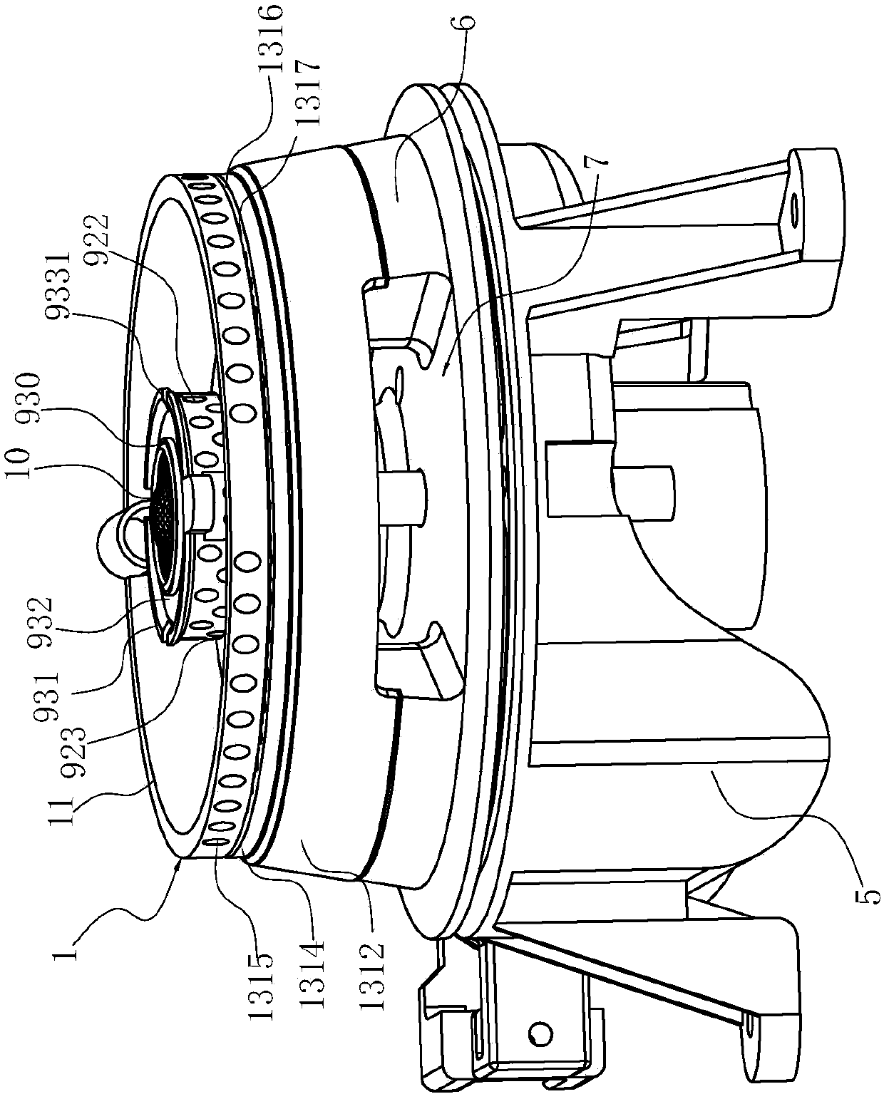
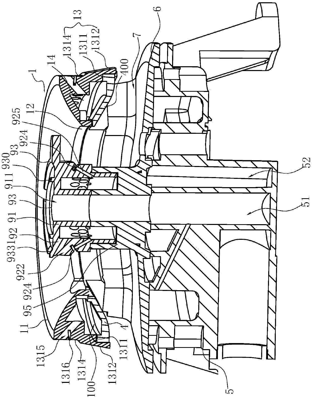
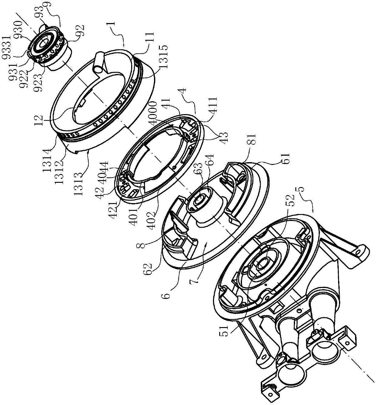
[0042] Such as Figure 1-10 Shown is the preferred embodiment of the present invention. In this embodiment, the burner used for the gas stove includes a first fire cover 1, and the first fire cover 1 includes a fire cover body, the annular top wall 11 of the fire cover body and the inner side A first air mixing chamber 14 is formed between the inner ring wall 12 and the outer ring wall 13 extending vertically downwards at the edge and the outer edge, and there are at least two first partitions 2 on the lower surface of the ring-shaped top wall 11 , There is a first distance D1 between adjacent first partitions 2, and a second partition 3 arranged on the lower surface of the annular top wall 11 and spaced apart from the first partition 2. In this embodiment, the first partition 2 and the second partition 3 are arranged oppositely, and there i...


PUM


Abstract

The invention relates to a combustor for a gas stove. The combustor comprises a first flame cover, and the first flame cover comprises a flame cover body. A first air mixing cavity is formed among theannular top wall of the flame cover body, and an inner ring wall and an outer ring wall which vertically extend downwards from the inner side edge and the outer side edge of the annular top wall. Thecombustor is characterized by further comprising a lower sealing plate capable of covering the bottom of the first air mixing cavity; and the lower sealing plate can move relative to the first flamecover, and the area of an opening, for allowing mixed air to be input, of the lower sealing plate is changed. Compared with the prior art, the combustor has the advantages that due to the fact that afirst air mixing chamber formed by the lower sealing plate and the first flame cover is designed to be of a split structure, and cleaning is convenient; and meanwhile, the lower sealing plate can moverelative to the first flame cover to achieve the gas outlet area of mixed gas in the first flame cover, the first flame cover large in gas outlet area is suitable for liquefied gas and other gas sources high in heat value, and the first flame cover small in gas outlet area can be suitable for natural gas, artificial gas and other gas sources low in heat value.

Description

technical field [0001] The invention relates to the field of gas cookers, in particular to a burner. Background technique [0002] The gas burner of the existing domestic gas cooker includes a gas mixing chamber, a first fire cover, an ejector tube, etc., wherein the gas mixing chamber of the burner is a very important part of the cooking range, and the function of the gas mixing chamber is to mix the gas so that the gas Mix with the primary air more evenly; supply secondary air to the inner ring at the same time, the current integrated fixed structure of the gas mixing chamber is not conducive to the cleaning of the cooker, especially the inside of the gas mixing chamber and the inside of the waist-shaped hole, the user is not easy to clean the gas mixing chamber There are also more and more complaints, such as the Chinese utility model patent "A Burner" with the patent number ZL201420072885 (the announcement number is CN2037314112U), or if the patent number is ZL2006100523...

Claims


Application Information

Patent Timeline
Patent Type & Authority Applications(China)
IPC IPC(8): F23D14/02F23D14/26F23D14/46F23D14/58F23D14/62F23L9/00
CPCF23D14/02F23D14/26F23D14/62F23D14/46F23D14/58F23L9/00F23D2900/14062
Inventor 刘晓刚柯情王帅东徐强郑军妹
Owner NINGBO FOTILE KITCHEN WARE CO LTD
Why Eureka
Try Eureka