
Computer Network Monitoring Device

A computer network and monitoring device technology, applied in the field of network security, can solve the problems of loose plugs, difficult to clean, network cables falling off, etc., to achieve the effect of improving stability, improving efficiency, and preventing dust from entering

Active Publication Date: 2020-07-03
海南经贸职业技术学院
View PDF7 Cites 0 Cited by
  • Summary
  • Abstract
  • Description
  • Claims
  • Application Information

AI Technical Summary

Problems solved by technology

[0002] In daily work, computers need to rely on the network for information transmission, reception, and sharing. With the development of network technology, network security has become a key issue in the field of computer networks and their applications. In order to prevent the network from being attacked and destroyed by hackers, users usually need to install The network monitoring device performs filtering and anti-blocking to avoid the leakage of important information. However, the current technical considerations are not perfect, and it has the following disadvantages: 1. The network monitoring device usually has many devices connected and the interfaces are dense, so the network cables of the LAN connection port are intertwined and intertwined. When unplugging one of the network cables, it is inevitable to touch other network cables, which will cause shaking and pulling of other network cables. For a long time, the plug on the outside of the computer network monitoring device will become loose, causing the network cable to fall off and affecting the monitoring work. 2. When an interface has not been used for a long time, a large amount of dust will accumulate in the interface slot, and the interface is small and difficult to clean, often resulting in the situation that the data cannot be read normally after the network cable is inserted, affecting information transmission

Method used


Image

  • Computer Network Monitoring Device
  • Computer Network Monitoring Device
  • Computer Network Monitoring Device

Examples


Embodiment

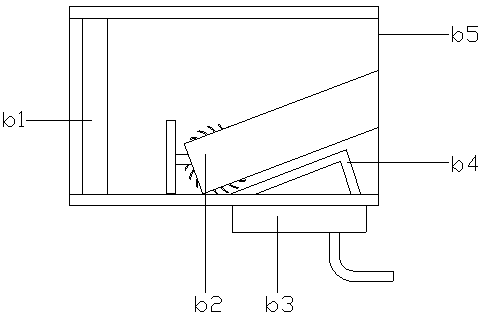
[0026] see Figure 1-Figure 2 , the present invention provides a computer network monitoring device, the structure of which includes a signal transmission antenna 1, a monitoring device main body 2, a cooling hole 3, a power connection hole 4, and a working indicator light 5. The monitoring device main body 2 is a rectangular structure, and the cooling hole 3 are evenly distributed on the right side of the monitoring equipment main body 2, the power connection hole 4 is nested behind the cooling hole 3 and is electrically connected to the monitoring equipment main body 2, and the working indicator light 5 is installed on the upper surface of the monitoring equipment main body 2 , the signal transmission antenna 1 is provided with two and fixed on the left and right sides of the back of the monitoring equipment main body 2 by bolts respectively. Board 2d, the equipment protection shell 2a is a hollow rectangular structure, the anti-slip gasket 2c is provided with four and the u...


PUM


Abstract

The invention discloses a computer network monitoring device. The structure of the device comprises a signal transmission antenna, a monitoring device main body, heat dissipation holes, a power supplyconnecting hole and a work indicating lamp. The network monitoring device is combined with a contact piece cleaning structure through a sealing dustproof device. When a network cable plug is connected with the network monitoring device, a local area network connector utilizes negative pressure to fix the plug, so that a network cable is prevented from touching other network cables to cause looseness and falling of a network cable interface when the network cable is mounted and dismounted, thereby improving the stability of receiving a network monitoring signal. Meanwhile, during the installation of the network cable, the contact parts of the local area network connector are cleaned, thereby avoiding the situation that signals cannot be normally transmitted after the network cables are inserted due to dust impurities, and improving the network monitoring signal transmission efficiency.

Description

technical field [0001] The invention relates to the technical field of network security, in particular to a computer network monitoring device. Background technique [0002] In daily work, computers need to rely on the network for information transmission, reception, and sharing. With the development of network technology, network security has become a key issue in the field of computer networks and their applications. In order to prevent the network from being attacked and destroyed by hackers, users usually need to install The network monitoring device performs filtering and anti-blocking to avoid the leakage of important information. However, the current technical considerations are not perfect, and it has the following disadvantages: 1. The network monitoring device usually has many devices connected and the interfaces are dense, so the network cables of the LAN connection port are intertwined and intertwined. When unplugging one of the network cables, it is inevitable t...

Claims


Application Information

Patent Timeline
Patent Type & Authority Patents(China)
IPC IPC(8): H01R13/502H01R13/52H01R13/627H01R13/629H01R13/73
CPCH01R13/502H01R13/5202H01R13/627H01R13/629H01R13/73
Inventor 何书鸾
Owner 海南经贸职业技术学院
Learn More