
Battery pack heating equipment, heat storage equipment and electric vehicles

A technology of heating equipment and battery packs, applied in the field of machinery, can solve problems such as temperature sensitivity of chemical power sources, difficulty in charging batteries at low temperature, and difficulty in starting electric vehicles at low temperature

Active Publication Date: 2021-09-14
HUAWEI DIGITAL POWER TECH CO LTD
View PDF15 Cites 0 Cited by
  • Summary
  • Abstract
  • Description
  • Claims
  • Application Information

AI Technical Summary

Problems solved by technology

[0002] With the promotion of electric vehicles, electric vehicles will be used in more and more environments. When electric vehicles run in winter in cold regions, it will be difficult to charge the battery at low temperature. Due to the difficulty of charging the battery at low temperature, In turn, there will be insufficient power to support the start of the electric vehicle, which will make it difficult to start the electric vehicle at low temperature. After starting, there will be problems such as low battery life and weak battery life.
Since the chemical power source itself is relatively sensitive to temperature, it is difficult to solve the above problems by changing the battery material and relying on changing the battery itself.
[0003] In order to improve the application ability of electric vehicles in cold regions, it is proposed in the prior art to use PTC heaters to heat the battery pack to increase the temperature of the battery pack, thereby solving the difficulties of low-temperature charging, low-temperature starting of electric vehicles, and shortened cruising range. question
[0004] However, the heating method using PTC heaters provided in the prior art not only has the problem of slow heating, but also consumes a lot of heat. Therefore, it is urgent to introduce a more environmentally friendly and energy-saving battery pack heating solution.

Method used


Image

  • Battery pack heating equipment, heat storage equipment and electric vehicles
  • Battery pack heating equipment, heat storage equipment and electric vehicles
  • Battery pack heating equipment, heat storage equipment and electric vehicles

Examples


Embodiment Construction

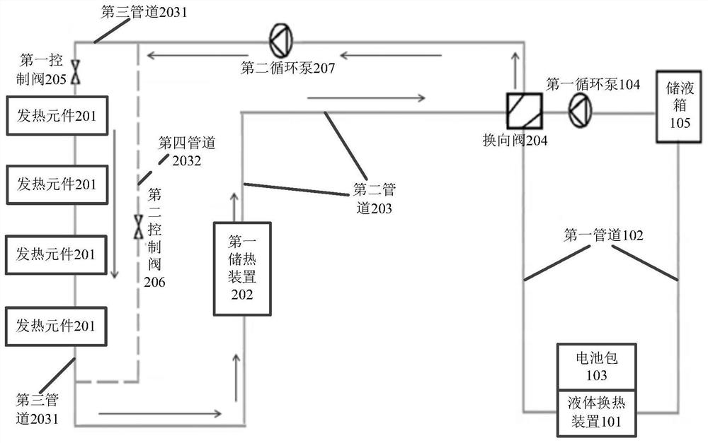
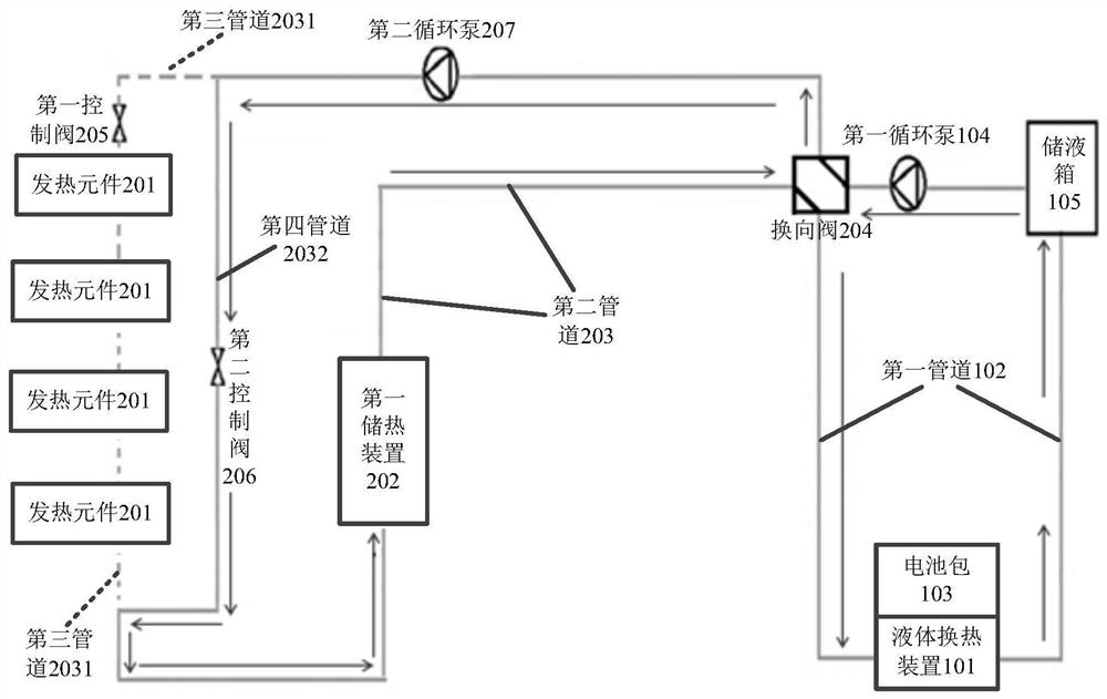
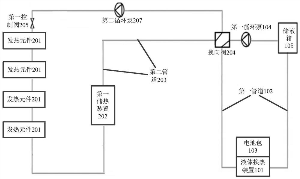
[0046] The embodiment of the present application provides a battery pack heating device, a heat storage device and an electric vehicle, which are used to store the heat generated by the heating element in the first heat storage device, and use the heat stored in the first heat storage device for Heating the battery pack means using the waste heat generated by other heating elements to heat the battery pack, thus providing an environmentally friendly and energy-saving battery pack heating solution.

[0047] The terms "first", "second", "third", "fourth", etc. (if any) in the description and claims of this application and the above drawings are used to distinguish similar objects and not necessarily Describe a particular order or sequence. It is to be understood that the terms so used are interchangeable under appropriate circumstances such that the embodiments described herein can be practiced in sequences other than those illustrated or described herein. Furthermore, the term...


PUM

PropertyMeasurementUnit
critical temperatureaaaaaaaaaa
phase transition temperatureaaaaaaaaaa

Abstract

The embodiment of the present application discloses a battery pack heating device, which can be applied to electric vehicles. The battery pack heating device includes a battery pack system and a heating system. The battery pack system is used to heat the battery pack. The heating system includes at least one There is a reversing valve between the heating element and the first heat storage device, the battery pack system and the heating system, and the reversing valve is used to control the connection and shutdown of the battery pack system and the heating system. The heat generated by the element can be stored in the first heat storage device. In the connected state, the heat stored in the first heat storage device can be used to heat the battery pack, and the waste heat generated by the heating element can be used to heat the battery pack, thus providing An environmentally friendly and energy-saving battery pack heating scheme is proposed.

Description

technical field [0001] The present application relates to the field of mechanical technology, in particular to a battery pack heating device, a heat storage device and an electric vehicle. Background technique [0002] With the promotion of electric vehicles, electric vehicles will be used in more and more environments. When electric vehicles run in winter in cold regions, it will be difficult to charge the battery at low temperature. Due to the difficulty of charging the battery at low temperature, In turn, there will be insufficient power to support the start of the electric vehicle, which will make it difficult to start the electric vehicle at low temperature. After starting, there will be problems such as low battery life and weak battery life. Since the chemical power source itself is relatively sensitive to temperature, it is difficult to solve the above problems by changing the battery material itself and relying on changing the battery itself. [0003] In order to i...

Claims


Application Information

Patent Timeline
Patent Type & Authority Patents(China)
IPC IPC(8): H01M10/615H01M10/625H01M10/6568H01M10/667H01M10/663H01M10/659H01M10/657H01M10/6556H01M10/655H01M10/658H01M10/635H01M10/633B60L58/27
CPCH01M10/615H01M10/625H01M10/6568H01M10/667H01M10/663H01M10/659H01M10/657H01M10/6556H01M10/655H01M10/658H01M10/635H01M10/633B60L58/27H01M2220/20Y02T10/70Y02E60/10
Inventor 何欢
Owner HUAWEI DIGITAL POWER TECH CO LTD
Learn More