
Circuit overload protection and replacement protection method

A circuit and insurance tube technology, applied in the field of circuit protectors, to achieve the effect of improving convenience, enhancing electricity safety, and ingenious structure

Active Publication Date: 2019-08-09
WENLING SHENLONG ELECTROMECHANICAL
View PDF5 Cites 2 Cited by
  • Summary
  • Abstract
  • Description
  • Claims
  • Application Information

AI Technical Summary

Problems solved by technology

[0002] The fuse is one of the very important circuit components. If the fuse is placed correctly in the circuit, the fuse will fuse itself to cut off the current when the current abnormally rises to a certain height and heat, which protects the safe operation of the circuit. The normal operation of the circuit plays an irreplaceable role. As the circuit of the fuse application becomes more and more complex, multi-functional and intelligent circuit fuse protectors appear on the market. However, at present, simple fuses or complex fuse protectors are used in There are also certain defects in the process of use. When the fuse cuts off the circuit, it is necessary to manually replace the fuse / fuse protector after the fuse to re-connect the circuit to normal operation. The replacement of the fuse / fuse protector requires power-off processing and mastering A certain common sense of electricity usage brings a lot of inconvenience to users. Therefore, the inventor designed a circuit fuse protector with ingenious structure and simple principle, which can replace the fuse after blown with one button and restore the circuit to normal operation. automatic follow-up conduction method

Method used


Image

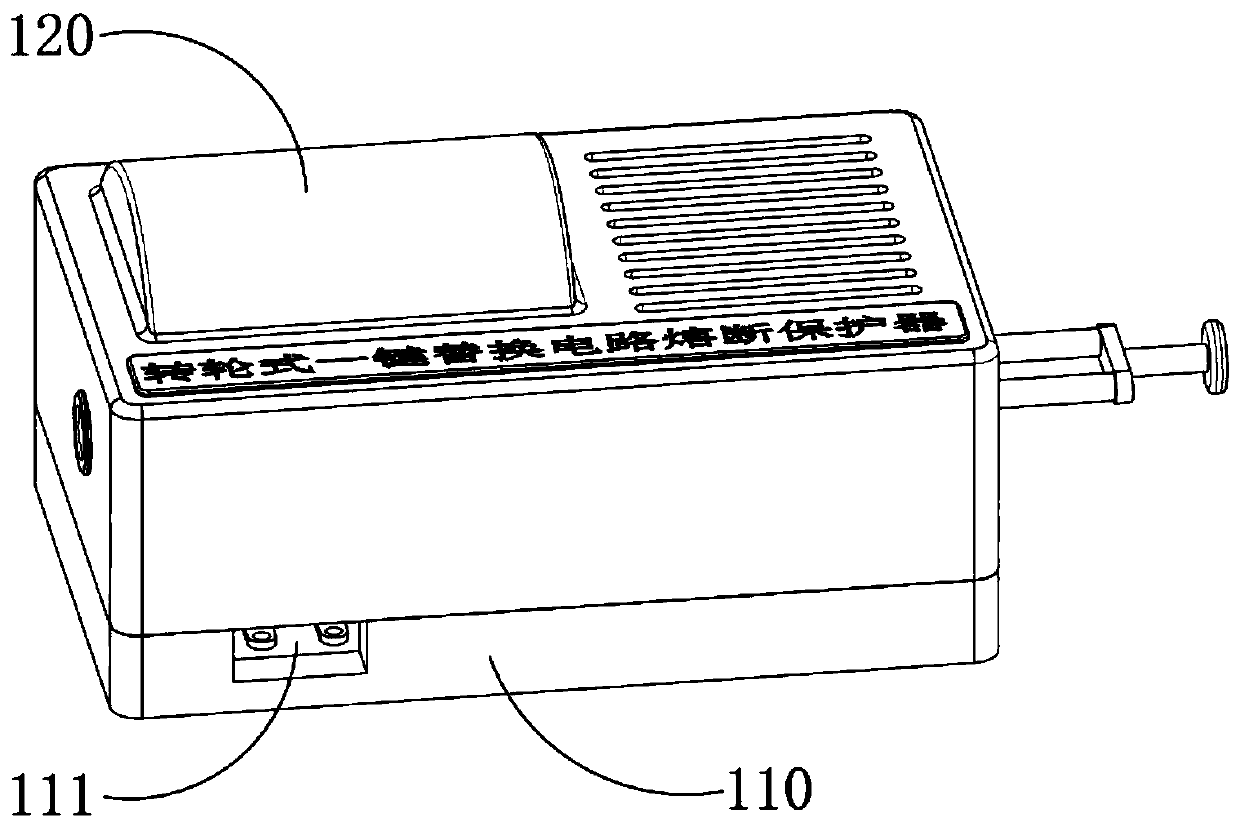
  • Circuit overload protection and replacement protection method
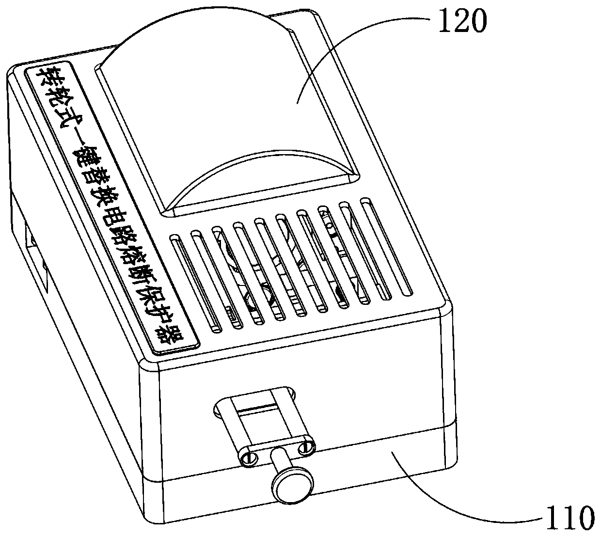
  • Circuit overload protection and replacement protection method
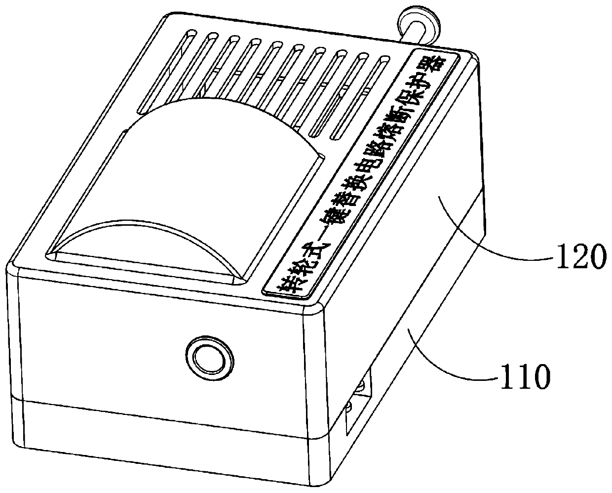
  • Circuit overload protection and replacement protection method

Examples


Embodiment Construction

[0070] The overload protection of the circuit and the method for replacement protection, the steps are as follows:

[0071] (1) Fuse protection stage;

[0072] S1: When the circuit current increases abnormally, the safety tube assembly in the rotation insurance mechanism 220 connected in series with the docking mechanism 210 will fuse, the input end and the output end of the docking mechanism 210 will be disconnected, and the live wire circuit will be disconnected for self-protection;

[0073] The docking mechanism 210 includes a vertical plate 211 arranged at one end of the bottom plate 110 along the length direction. The vertical plate 211 is arranged along the width direction of the bottom plate 110. An insulating docking plate 212 is fixedly installed on the vertical plate 211. The docking plate 212 The axial direction of the base plate 110 is parallel to the length direction of the bottom plate 110. The end surface of the docking plate 212 close to the other end of the bo...


PUM


Abstract

The invention provides a circuit overload protection and replacement protection method. The method is characterized in that firstly, when the circuit current abnormally increases, a fuse assembly in series with a docking mechanism in a rotary fuse mechanism is blown out, an input end and an output end of the docking mechanism are disconnected, and a live-wire circuit is disconnected for self protection; secondly, the fuse assembly releases the internally stored elastic potential energy at the instant of fusing and triggers an ejection mechanism, and the ejection mechanism fires and pushes theblown fuse assembly out of a roller; and lastly, a user troubleshoots a circuit and properly handles faults, the user manually pulls a handle to reset, in the process, a flange provides the motive force to a rotary driving mechanism, the rotary driving mechanism automatically drives the roller to automatically rotate by forty-five degrees and makes an adjacent fuse assembly rotate to achieve movable pressing docking with the docking mechanism, at this point, the live wire is turned on, and the circuit resumes normal operation.

Description

technical field [0001] The invention relates to a circuit protector, in particular to a method for circuit overload protection and replacement protection. Background technique [0002] The fuse is one of the very important circuit components. If the fuse is placed correctly in the circuit, the fuse will fuse itself to cut off the current when the current abnormally rises to a certain height and heat, which protects the safe operation of the circuit. The normal operation of the circuit plays an irreplaceable role. As the circuit of the fuse application becomes more and more complex, multi-functional and intelligent circuit fuse protectors appear on the market. However, at present, simple fuses or complex fuse protectors are used in There are also certain defects in the process of use. When the fuse cuts off the circuit, it is necessary to manually replace the fuse / fuse protector after the fuse to re-connect the circuit to normal operation. The replacement of the fuse / fuse pro...

Claims


Application Information

Patent Timeline
Patent Type & Authority Applications(China)
IPC IPC(8): H01H85/22H01H85/02
CPCH01H85/0208H01H85/22
Inventor 梁根如
Owner WENLING SHENLONG ELECTROMECHANICAL
Learn More