Bidirectional self-holding electromagnet for achieving position stability based on spring pressure and reluctance force
A technology of spring pressure and magnetic resistance, applied to electromagnets with armatures, electromagnets, circuits, etc., can solve the problems of high power consumption of electromagnets, reduced holding force, and coil heating, etc. The effect of large value and simple structure
- Summary
- Abstract
- Description
- Claims
- Application Information
AI Technical Summary
Problems solved by technology
Method used
Image
Examples
specific Embodiment approach 1
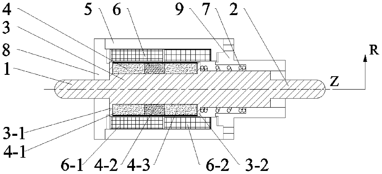
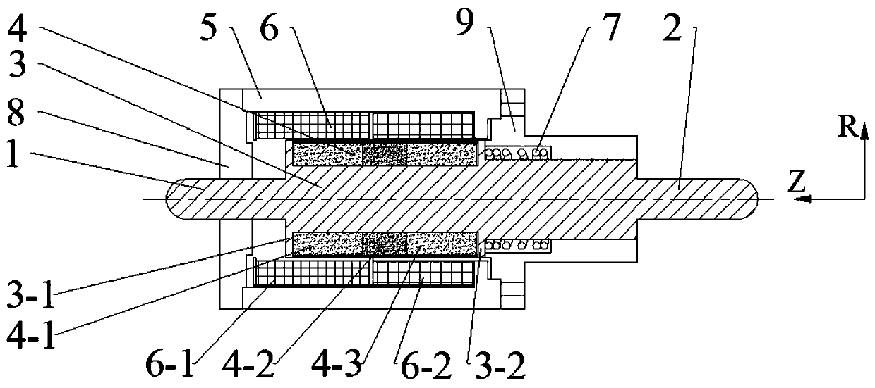
[0011] Specific implementation mode one: combine Figure 1 to Figure 4 Describe this embodiment, the two-way holding electromagnet of this embodiment comprises yoke 5, moving core 3, and described yoke 5 is provided with cavity, and moving core 3 is positioned at the cavity of yoke 5, and the left end of moving core 3 There is a left push rod 1, and the right end of the moving core 3 is provided with a right push rod 2, which is characterized in that: the present invention also includes a permanent magnet 4, a helical coil 6 and a spring 7, the permanent magnet 4 is a hollow cylinder, and the permanent magnet is sleeved on On the moving core, the helical coil 6 is wound on the outer periphery of the permanent magnet 4, and the spring 7 is sleeved on the outer surface of the right push rod 2.
[0012] There is an air gap between the yoke 5 and the moving core 3, the spring 7 is located between the teeth of the right moving core and the inner surface of the right end cover, and ...
specific Embodiment approach 2
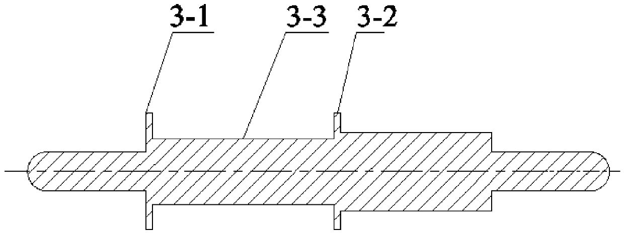
[0015] Specific implementation mode two: combination Figure 1 to Figure 3 Describe this embodiment, the left movable core tooth 3-1 is provided between the movable core 3 and the left push rod 1 of this embodiment, the right movable core tooth 3-2 is provided between the movable core 3 and the right push rod 9, and the left A moving core slot 3-3 is formed between the moving core tooth 31 and the right moving core tooth 32, and the permanent magnet 4 is located in the moving core slot 3-3. Other compositions and connections are the same as in the first embodiment.
specific Embodiment approach 3
[0016] Specific implementation mode three: combination Figure 1 to Figure 3 To describe this embodiment, the wall thickness of the permanent magnet 4 in this embodiment is not greater than the depth of the moving core groove 3-3. In this arrangement, in order to facilitate the coating treatment of the permanent magnet, the thickness of the outer diameter of the permanent magnet is slightly smaller than the depth of the moving core groove 3-3. Other compositions and connections are the same as those in Embodiment 1 or Embodiment 2.
PUM
 Abstract
Description
Claims
Application Information
 - R&D
- Intellectual Property
- Life Sciences
- Materials
- Tech Scout
- Unparalleled Data Quality
- Higher Quality Content
- 60% Fewer Hallucinations
Browse by: Latest US Patents, China's latest patents, Technical Efficacy Thesaurus, Application Domain, Technology Topic, Popular Technical Reports.
© 2025 PatSnap. All rights reserved.Legal|Privacy policy|Modern Slavery Act Transparency Statement|Sitemap|About US| Contact US: help@patsnap.com


