
Evaluation method of binary grating projection defocus degree based on image difference and lm iteration

An image difference and binary grating technology, applied in the direction of optical devices, instruments, measuring devices, etc., can solve the problems that are not conducive to the development of high-precision photomechanics, the pattern is not a sinusoidal curve, and affect the accuracy of measurement, etc., to achieve intuitiveness Strong, high accuracy, satisfying the effect of real-time calculation

Active Publication Date: 2021-04-16
NANJING UNIV OF SCI & TECH
View PDF21 Cites 0 Cited by
  • Summary
  • Abstract
  • Description
  • Claims
  • Application Information

AI Technical Summary

Problems solved by technology

There are however some problems with the binary defocus technique: if the degree of defocus is too small, the pattern is not sinusoidal and contains many higher harmonics
The non-sinusoidal structure is caused by high-order harmonics in the binary defocusing technique, which introduces errors into the demodulation phase, which reduces the accuracy of 3D measurements
In addition, in practical applications, if you want to improve the accuracy of measurement, you must consider the problem that the received image has certain non-sinusoidal characteristics due to the β distortion of the electronic device itself.
Such problems affect the accuracy of measurement and are not conducive to the development of high-precision photomechanics

Method used


Image

  • Evaluation method of binary grating projection defocus degree based on image difference and lm iteration
  • Evaluation method of binary grating projection defocus degree based on image difference and lm iteration
  • Evaluation method of binary grating projection defocus degree based on image difference and lm iteration

Examples


Embodiment

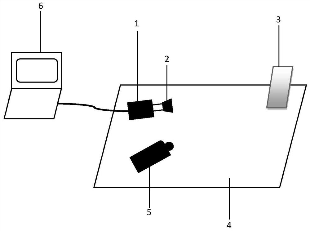
[0039] Such as figure 1 As shown, a binary grating projection defocus evaluation method based on image difference and LM (Levenberg-Marquardt) iteration, the method experimental device includes the following equipment: an industrial camera 1, high-resolution lens 2, optical platform 4 , an electronic computer 6, a projector 5, a plane calibration plate with low reflectivity and a clamping device 3 thereof. The industrial camera used in the test experiment has a pixel of 4 million pixels and a lens focal length of 35mm. Such as figure 2 As shown, the evaluation method includes the following steps:

[0040] Step 1. Fixing of the experimental device: Fix the calibration board, camera and projector tightly on the optical platform to limit the relative displacement between each part; during this process, the camera lens should be perpendicular to the plane of the calibration board, and the projection Position the instrument lens in the direction of the largest plane of the cali...


PUM


Abstract

The invention discloses a method for evaluating defocus degree of binary grating projection based on image difference and LM iteration. The method for evaluating defocus degree includes the following steps: adjusting the parameters of the output grating of the projector before testing; The image acquired by the camera performs a differential operation, and then performs an iterative operation on the differential image through the LM method for the sinusoidal objective function; obtains the data at each point of the image at the end of the iteration and the absolute error of the actual image, and corrects it with the gray scale of the image. Reduce fluctuation errors. The present invention evaluates the degree of defocus from an experimental point of view, and has the advantages of high accuracy in judging the degree of defocus, simple required equipment, convenience and practicality, real-time display and the like.

Description

technical field [0001] The invention relates to the field of optical measurement experiment solid mechanics, in particular to a method for evaluating defocus degree of binary grating projection based on image difference and LM iteration. Background technique [0002] In the field of photomechanics, the grating projection method is a basic optical shape measurement method. The grid line projection method directly uses the phase distortion information of the modulated grid line to obtain the three-dimensional information of the object, and uses a mathematical method to demodulate the phase, and can automatically determine the concave-convexity of the object. Therefore, image processing is easy to automate, and has high precision and sensitivity. [0003] For ease of measurement, in the grid projection method, the projector projects a 2D structural pattern (stripe pattern) instead of a 3D shaped sinusoidal pattern, and then the binary pattern is blurred into a quasi-sinusoidal...

Claims


Application Information

Patent Timeline
Patent Type & Authority Patents(China)
IPC IPC(8): G01B11/24
CPCG01B11/2433
Inventor 刘聪尹卓异刘晓鹏梅林
Owner NANJING UNIV OF SCI & TECH
Learn More