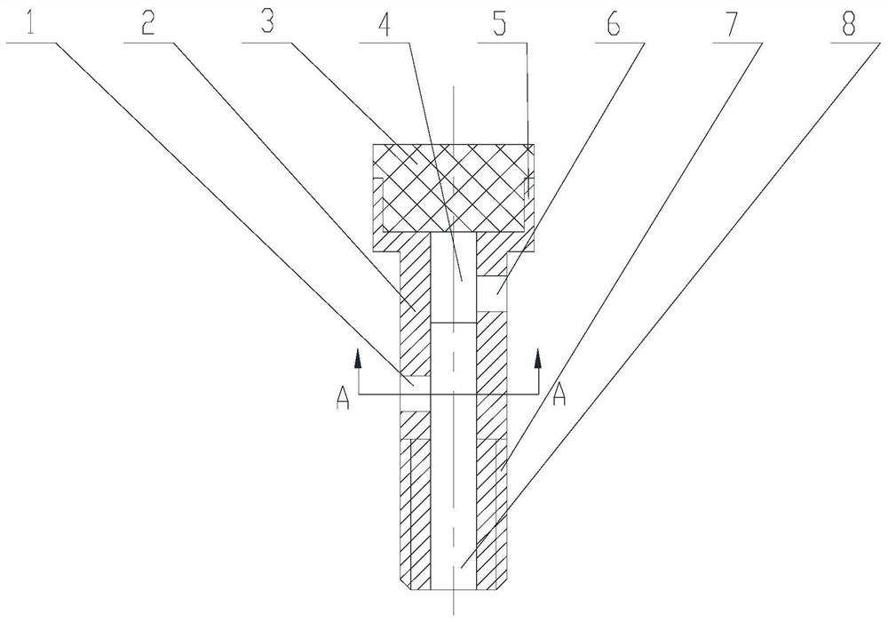
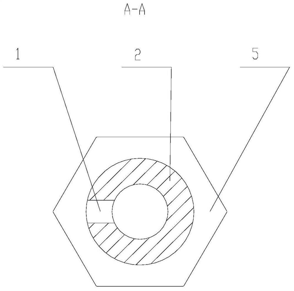
An oil supply hollow screw structure

A hollow screw, screw technology, applied in valve details, valve device, machine/engine, etc., can solve problems such as supercharger oil leakage

Active Publication Date: 2020-10-09
CHINA NORTH ENGINE INST TIANJIN
View PDF9 Cites 0 Cited by
  • Summary
  • Abstract
  • Description
  • Claims
  • Application Information

AI Technical Summary

Problems solved by technology

[0003] In view of this, the present invention aims to propose a hollow screw structure for oil supply, which can be connected to the main oil passage of the engine to supply oil for the sequential supercharging system, so as to solve the problem of the controlled supercharger of the existing sequential supercharging system. Low speed, low load does not work, when the turbine rotor does not rotate, the oil leakage problem at the turbine end seal ring of the supercharger

Method used


Image

  • An oil supply hollow screw structure
  • An oil supply hollow screw structure

Examples


Embodiment Construction

[0015] It should be noted that, in the case of no conflict, the embodiments of the present invention and the features in the embodiments can be combined with each other.

[0016] In describing the present invention, it should be understood that the terms "center", "longitudinal", "transverse", "upper", "lower", "front", "rear", "left", "right", " The orientations or positional relationships indicated by "vertical", "horizontal", "top", "bottom", "inner" and "outer" are based on the orientations or positional relationships shown in the drawings, and are only for the convenience of describing the present invention and Simplified descriptions, rather than indicating or implying that the device or element referred to must have a particular orientation, be constructed and operate in a particular orientation, and thus should not be construed as limiting the invention. In addition, the terms "first", "second", etc. are used for descriptive purposes only, and should not be understood ...


PUM


Abstract

The invention provides a hollow fuel feeding screw structure. The hollow fuel feeding screw structure comprises a screw body with a through hole formed in the axis, and an electromagnetic valve, wherein the screw body comprises a screw head and a screw stem which are formed integrally, a controlled supercharger fuel feeding port and a main supercharger fuel feeding port which communicate with thethrough hole and are placed in staggered mode are formed in the side wall of the screw stem, the position of the controlled supercharger fuel feeding port is close to the screw head, the electromagnetic valve is arranged on the screw head, and a cylindrical piston at the bottom of the electromagnetic valve is arranged in the through hole in the screw body in telescopic mode. When the electromagnetic valve controls the piston to contract towards the screw head, both the controlled supercharger fuel feeding port and the main supercharger fuel feeding port communicate with the through hole in thescrew body. When the electromagnetic valve controls the piston to stretch out, only the main supercharger fuel feeding port communicates with the through hole in the screw body. The hollow fuel feeding screw structure solves the problem that when an engine does not work under low velocity and low load and a turbine rotor does not rotate, fuel leaks from a sealing ring at a turbine end of a controlled supercharger of an existing sequential supercharging system.

Description

technical field [0001] The invention belongs to the field of electromechanical technology, and in particular relates to an oil supply hollow screw structure. Background technique [0002] Some high-power diesel engines have a variety of operating conditions and a large power span. A sequential supercharging system is required to achieve the adjustment of the supercharged air flow. However, the sequential supercharging system brings some problems: when the controlled supercharger of the prior art does not work at low speed and low load of the engine, the oil inlet of the bearing body of the controlled supercharger maintains a certain oil supply pressure all the time, and the lubrication The oil continuously flows through the fitting gap of the supercharger bearing system, and flows into the oil return chamber of the bearing body. A part of the lubricating oil splashes onto the seal ring at the turbine end, and leaks to the back of the turbine wheel through the gap of the seal...

Claims


Application Information

Patent Timeline
Patent Type & Authority Patents(China)
IPC IPC(8): F02B39/14F16K31/06
CPCF02B39/14F16K31/06
Inventor 王振彪邓春龙
Owner CHINA NORTH ENGINE INST TIANJIN
Why Eureka
Try Eureka