
Tank-wall heat tracing dirty oil sedimentation method and device

A settling device and technology for dirty oil, applied in the direction of separation method, grease/oily substance/suspended substance removal device, chemical instrument and method, etc., can solve unfavorable gravity settlement, poor separation effect of sewage oil settlement, and inconspicuous dehydration effect, etc. problem, to achieve the effect of effective separation

Pending Publication Date: 2019-08-09
QINGDAO BESTSONIC TECH CO LTD
View PDF0 Cites 2 Cited by
  • Summary
  • Abstract
  • Description
  • Claims
  • Application Information

AI Technical Summary

Problems solved by technology

In order to further increase the dehydration rate of the waste oil and reduce the water content of the waste oil to <5%, the steam heating of the tank bottom pan pipe is turned on, the temperature of the waste oil tank is heated to 90°C, the clear water layer at the bottom of the waste oil tank disappears, and the average water content of the waste oil The dehydration rate increased to 55%, and the ultrasonic effect was performed again for 30 days, and the dehydration effect was not obvious
[0005] The design of the waste oil tank generally follows the heating method of the tank bottom of the crude oil tank, and the existing defects are: the sedimentation and separation effect of the waste oil is poor, it is easy to mix back, it is not conducive to the gravity settlement process, and it is difficult to realize the oil-water residue of the waste oil Separation, resulting in the accumulation of aging oil, heavy dirty oil, and tank bottom sludge in the production plant, which has become a production problem for the production plant
[0006] The existing technical situation is that the waste oil in the production plant is stored in the crude oil tank or the waste oil tank. The heating method of the crude oil tank or the waste oil tank adopts the heating method of the bottom of the tank, and the oil-water residue separation of the waste oil cannot be effectively realized. The dirty oil in the production plant is accumulating more and more, which has become a production problem that the production plant needs to solve

Method used


Image

  • Tank-wall heat tracing dirty oil sedimentation method and device
  • Tank-wall heat tracing dirty oil sedimentation method and device

Examples


Embodiment 1

[0030] The invention discloses a tank wall heat tracing method for settling dirty oil. Specifically, the heat tracing method is evenly arranged from top to bottom along the height of the tank, and the temperature of the heat tracing medium is controlled to be less than 100°C, so as to achieve three-phase separation of oil, water, and slag of the waste oil.

[0031] The heating medium is heat medium water.

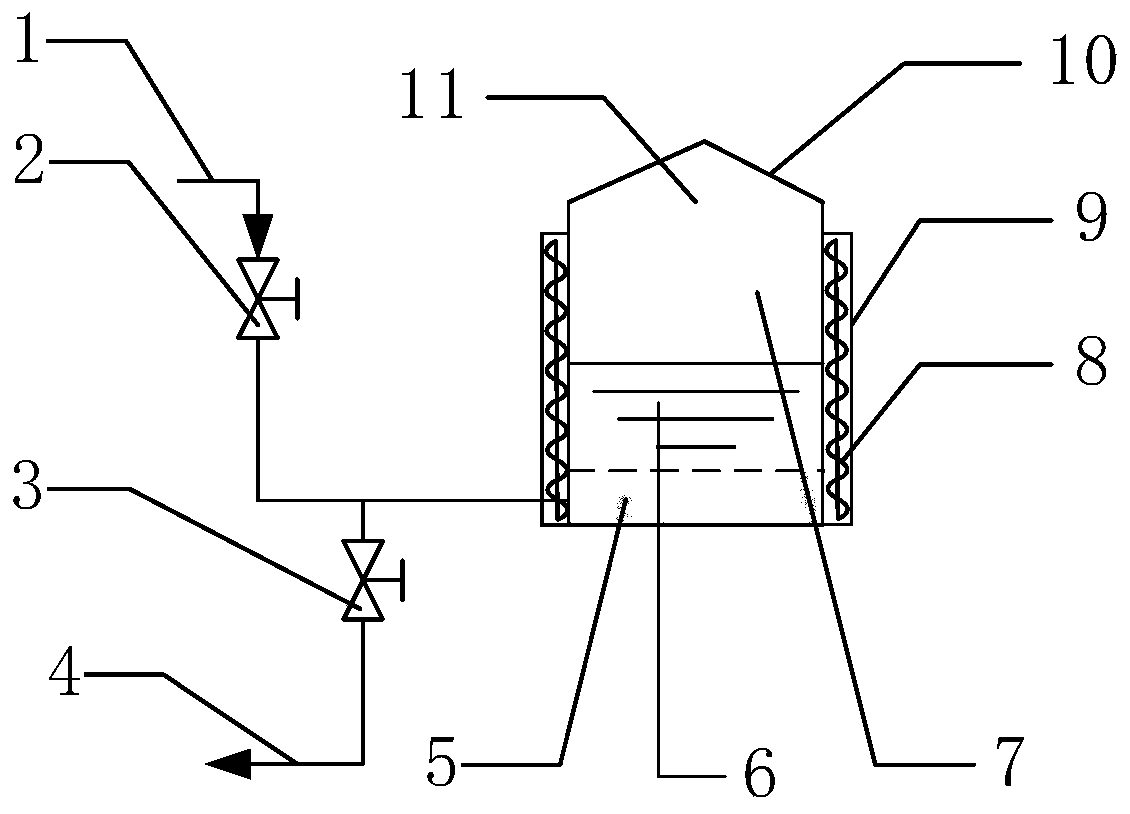
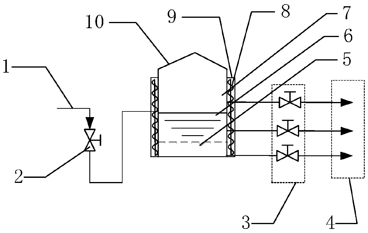
[0032] A tank wall heating type sewage oil settling device, comprising a feed sewage oil pipeline 1, a feed sewage oil pipeline 1 connected to a feed switch valve 2 through a pipeline, and a feed switch valve 2 connected to a settling tank 11 through a pipeline The settling tank 11 includes a tank body 10, the upper part of the tank body 10 is a cone, and the lower part is a cylinder. The heating line 8 is arranged outside the lower cylinder of the tank body 10, and the heat insulation layer 9 is arranged outside the heating line 8.

[0033] The heating line 8 is arranged e...

Embodiment 2

[0047] The invention relates to a method for settling waste oil with heat tracing on the tank wall. The heat tracing method is evenly arranged from top to bottom along the height of the tank, and the temperature of the heat tracing medium is controlled to be less than 100°C, so as to achieve the three-phase separation of oil, water, and slag of the waste oil.

[0048] The tank wall heating type sewage oil settling device used in Example 2 is the same as that in Example 1.

[0049] A kind of tank wall heating type sewage oil settling device, refer to figure 1 method, transforming the 200L settling tank, and evenly installing silica gel electric heating cables from bottom to top along the tank wall, and settling and separating the dirty oil that could not be effectively separated in Comparative Example 1, settling at 90°C for 5 days, and separating the oil and water slag The effect is obvious. Divide 10 sampling points equally along the height of the settling tank, and analyze ...

Embodiment 3

[0051] The invention relates to a method for settling waste oil with heat tracing on the tank wall. The heat tracing method is evenly arranged from top to bottom along the height of the tank, and the temperature of the heat tracing medium is controlled to be less than 100°C, so as to achieve the three-phase separation of oil, water, and slag of the waste oil.

[0052] A tank wall heating type sewage oil settling device, comprising a feed sewage oil pipeline 1, a feed sewage oil pipeline 1 connected to a feed switch valve 2 through a pipeline, and a feed switch valve 2 connected to a settling tank 11 through a pipeline The settling tank 11 includes a tank body 10, the upper part of the tank body 10 is a cone, and the lower part is a cylinder. The heating line 8 is arranged outside the lower cylinder of the tank body 10, and the heat insulation layer 9 is arranged outside the heating line 8.

[0053] The heating line 8 is arranged evenly from bottom to top along the height of the...


PUM


Abstract

The invention belongs to the technical field of dirty oil treatment, and particularly relates to a tank-wall heat tracing dirty oil sedimentation method and device. The device comprises a dirty oil feeding pipe, the dirty oil feeding pipe is connected with a feeding switch valve through a pipe, and the feeding switch valve is connected with a sedimentation tank; the sedimentation tank comprises atank body, the upper portion of the tank body is a cone, the lower portion of the tank body is a cylinder, heat tracing lines are arranged on the outer side of the lower cylinder of the tank body, anda thermal insulating layer is arranged outside the heat tracing lines. According to the tank-wall heat tracing dirty oil sedimentation method and device, the uniform-temperature dirty soil sedimentation device with heating, heat tracing and thermal insulating from bottom to top is provided, the technical problem of fluid convection in high-temperature and low-temperature areas of tank-bottom coiled-tube-type heating, heat tracing and temperature preservation of the dirty oil sedimentation tank under the general condition is solved, the top-down gravity sedimentation effect is ensured, and finally, effective separation of three phases of oil, water and residues is achieved.

Description

technical field [0001] The invention belongs to the technical field of waste oil treatment, and in particular relates to a method and device for settling waste oil with heat tracing on the tank wall. Background technique [0002] Slop oil is a type of high water content emulsified crude oil produced in the production process of oil fields or refineries. Some dirty oil is called heavy dirty oil. Heavy dirty oil has high content of mechanical impurities, high metal content, high content of solid suspended particles, high water content, high content of surfactant, etc. Heavy dirty oil mainly comes from crude oil tanks Sludge oil from processes such as undercut water, crude oil electric desalination water cut, equipment maintenance and line sweeping, sewage treatment grease trap recovery, etc.; Effective processing and utilization, after a long period of hydrothermal biochemical action, the treatment becomes more and more difficult, so it is called aging oil; the source and nat...

Claims


Application Information

Patent Timeline
IPC IPC(8): C02F1/40C02F103/10
CPCC02F1/40C02F2001/007C02F2103/365C02F2103/10
Inventor 苟泽浩崔建伟毛金柱连喜增齐杰张茂锋张达峰王涛张琳佳侯雪松
Owner QINGDAO BESTSONIC TECH CO LTD
Learn More