


Quick Research
Generate reliable direction feasibility study reports for your R&D in just a few steps.

Technical Q&A
Discover and master advanced knowledge NOW. Basics, ideas, possibilities, all at once.

Find Solutions
As an expert in R&D theories, this can generate solutions to your technical problems instantly.

Evaluate Feasibility
Analyze your overall solution with one click, know your potential R&D risks in advance.

Monitor Landscape
Get weekly tech updates, stay abreast of the latest tech innovations and key insights.
Power wingsuit
A power wing and power technology, applied in the field of flight equipment, can solve the problems of high risk and high mortality of flying wing equipment
- Summary
- Abstract
- Description
- Claims
- Application Information
AI Technical Summary
Problems solved by technology
Method used
Image

Examples
Embodiment 1
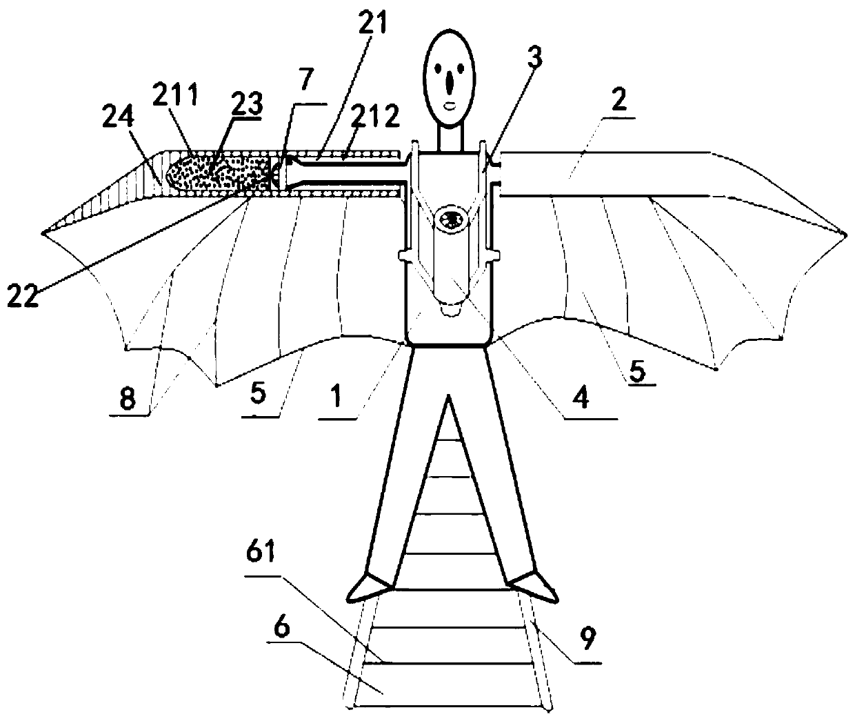
[0045] see figure 1, a powered wingsuit provided by the present invention, said powered wingsuit comprising: a flight suit 1 worn by pilots; two extension tubes 2, arranged horizontally on the outside of the shoulders of the pilots, the opposite ends of the two extension tubes 2 The opening and the other end are closed, and the inner side of the extension tube 2 forms a chamber 21 for the pilot to extend his arms into the inner side of the extension tube 2; the cage 3 is set on the flight suit 1 corresponding to the position of the upper body of the pilot; at least one powered flight device 4. Installed on the cage 3 corresponding to the position of the front chest or back of the pilot, the power injection end of the power flight device 4 faces the position of the feet of the pilot; the two flight membranes 5 correspond to the two extension tubes 2, so The side edge of the flight membrane 5 is connected to the lower surface of the outer wall of the extension tube 2 along the l...
Embodiment 2
[0065] An extension bar 9 is connected to the outer surface of the flight suit 1 corresponding to the soles of the pilot's feet to extend the length of the pilot's legs; an empennage membrane 6 is arranged between the two extension bars 9 .
[0066] Two stilt-type extension rods 9 are installed under the feet of the pilot, and the empennage membrane 6 is also sewn in the middle of the extension rods 9 to increase the control moment and area of the empennage.
[0067] All the other are with embodiment 1.
Embodiment 3
[0069] The outer surfaces of the flight wing membrane 5 and the empennage membrane 6 are respectively coated with a sealing drag-reducing coating film (not shown);
[0070] The flight membrane 5 and the empennage membrane 6 are fabrics such as high-strength nylon, which are coated with polymer materials, that is, the sealing and drag-reducing coating film is used to block air penetration and reduce the friction between the fabric and the air during flight to improve flight performance. speed.
[0071] All the other are with embodiment 1 or 2.
PUM
 Abstract
Description
Claims
Application Information
 - R&D Engineer
- R&D Manager
- IP Professional
- Industry Leading Data Capabilities
- Powerful AI technology
- Patent DNA Extraction
Browse by: Latest US Patents, China's latest patents, Technical Efficacy Thesaurus, Application Domain, Technology Topic, Popular Technical Reports.
© 2024 PatSnap. All rights reserved.Legal|Privacy policy|Modern Slavery Act Transparency Statement|Sitemap|About US| Contact US: help@patsnap.com