
Workpiece clamping equipment for milling

A clamping equipment and milling processing technology, which is applied in the field of milling processing, can solve the problems of inconvenient processing, difficulty in changing the clamping position, and low fit, so as to achieve the effect of improving the fit

Inactive Publication Date: 2019-08-09
DALIAN JIAOTONG UNIVERSITY
View PDF8 Cites 3 Cited by
  • Summary
  • Abstract
  • Description
  • Claims
  • Application Information

AI Technical Summary

Problems solved by technology

[0007] The object of the present invention is to provide a workpiece clamping device for milling, to solve the above background technology that the workpiece clamping device is difficult to change the clamping position, it is inconvenient to process various orientations of the workpiece and the joint degree of clamping is not good high problem

Method used


Image

  • Workpiece clamping equipment for milling
  • Workpiece clamping equipment for milling
  • Workpiece clamping equipment for milling

Examples


Embodiment Construction

[0024] The following will clearly and completely describe the technical solutions in the embodiments of the present invention with reference to the accompanying drawings in the embodiments of the present invention. Obviously, the described embodiments are only some, not all, embodiments of the present invention. Based on the embodiments of the present invention, all other embodiments obtained by persons of ordinary skill in the art without making creative efforts belong to the protection scope of the present invention.

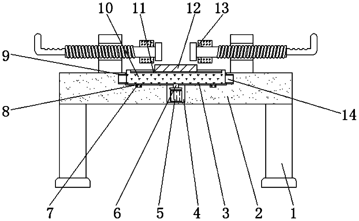
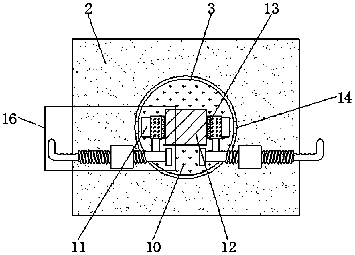
[0025] see Figure 1-5 , an embodiment provided by the present invention: a workpiece clamping device for milling, including an operating table 2, an annular groove 3, a turntable 10, a placing table 12 and a clamping mechanism 16, and the central position of the top of the operating table 2 is set There is an annular groove 3, and the inside of the annular groove 3 is provided with a turntable 10, the outer wall of the turntable 10 is fixed with a slider 14, ...


PUM


Abstract

The invention discloses workpiece clamping equipment for milling. The workpiece clamping equipment comprises an operation table, an annular groove, a rotating table, a containing table and clamping mechanisms. The annular groove is formed in the center position of the top end of the operation table, and the rotating table is arranged in the annular groove. The clamping mechanisms are arranged on the two sides of the top end of the operation table. A work cavity is formed in supporting columns, a servo motor is mounted in the work cavity, and a rotating shaft is mounted at the output end of theservo motor through a coupling. One end of the rotating shaft extends into the annular groove and s fixedly connected with the bottom end of the rotating table. The supporting columns are fixed to the corner positions of the bottom end of the operation table. A control panel is mounted on the outer walls of one sides of the supporting columns, and the output end of a single-chip microcomputer inthe control panel is electrically connected with the input end of the servo motor. According to the workpiece clamping equipment, the function that clamping positions can be adjusted is achieved, thefunction of adjusting of workpiece machining directions is also achieved, and the attachment degree between clamp plates and workpieces is improved.

Description

technical field [0001] The invention relates to the technical field of milling, in particular to a workpiece clamping device for milling. Background technique [0002] With the continuous development of society, more and more workpieces need to be processed. Milling is a cutting workpiece, and it is also a high-precision processing method. However, in the usual workpiece processing work, the workpiece is prone to deviation. The traditional The method requires the operator to fix it manually, but the safety is low, it is easy to accidentally injure the staff, and the operation is extremely inconvenient. [0003] There are many types of workpiece clamping equipment on the market today, which can basically meet people's needs, but there are still some deficiencies. The specific problems are as follows. [0004] (1) The traditional workpiece clamping equipment usually clamps the workpiece in a fixed mode when used, and it is usually difficult to change the clamping position, so...

Claims


Application Information

Patent Timeline
Patent Type & Authority Applications(China)
IPC IPC(8): B23Q3/06
CPCB23Q3/06
Inventor 朱建宁
Owner DALIAN JIAOTONG UNIVERSITY
Learn More