Easy-to-install paint mist filter bag and manufacturing method
A paint mist filter and filter bag technology, applied in the field of filters, can solve problems such as unstable structure, cumbersome operation, and increased wind resistance of the spray booth, and achieve the effect of reasonable structural design, large disassembly space, and not easy to lose
- Summary
- Abstract
- Description
- Claims
- Application Information
AI Technical Summary
Problems solved by technology
Method used
Image
Examples
Embodiment 1
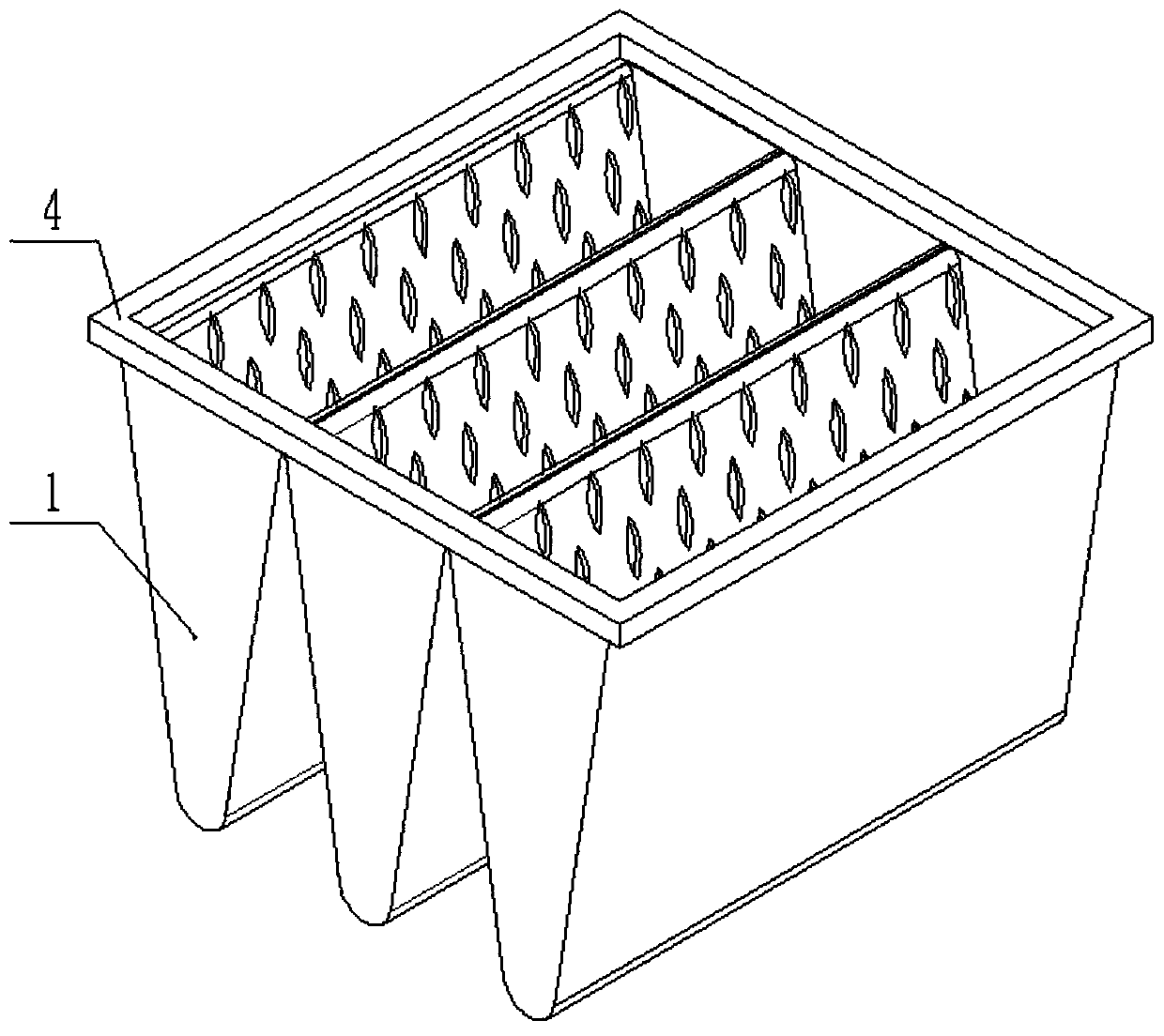
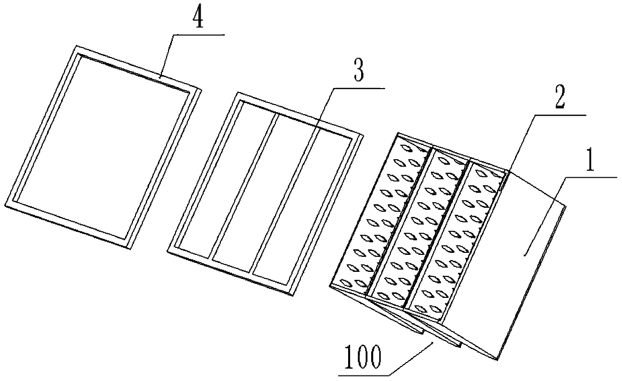
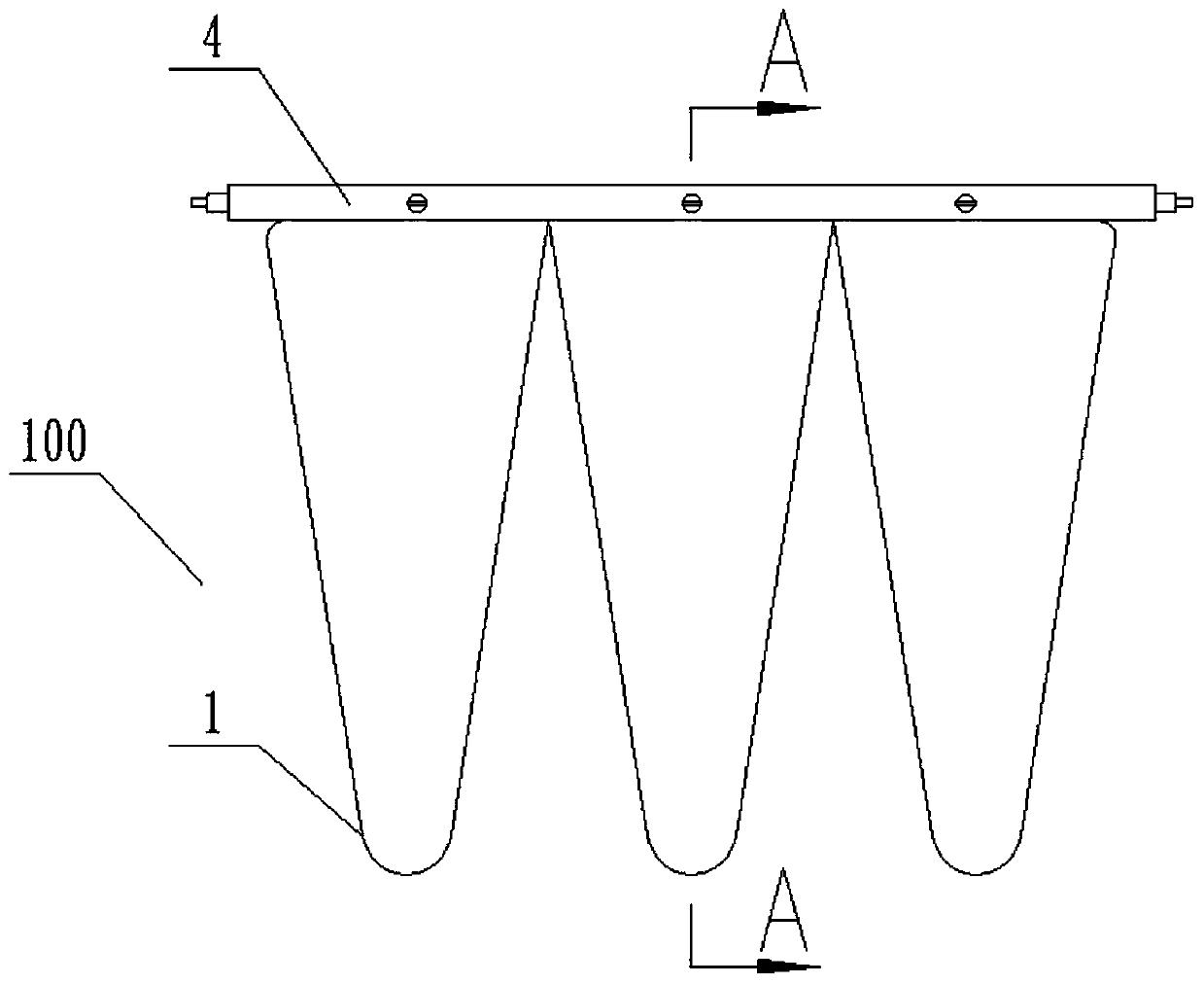
[0059] see Figure 1-7 as well as Figure 16 , the present invention provides a paint mist filter bag that is easy to install, including a filter bag body 100, the filter bag body 100 is composed of a plurality of filter bag monomers 1 arranged side by side, and the paint mist filter bag that is easy to install also includes a fixed frame 2 , internal connection box 3 and external connection box 4;
[0060] The above-mentioned fixed frame 2 is pressed and arranged at the opening of the filter bag monomer 1, and both sides of the fixed frame 2 are symmetrically provided with connecting lugs 21, and the shape of the connecting lugs is not limited to the shape shown in the accompanying drawings;
[0061] The above-mentioned internal connection frame 3 is embedded on the fixed frame 2, and the two side frames of the internal connection frame 3 are provided with connection grooves 31 recessed inwardly, and the bottom surface near the two ends is integrally provided with connection...
Embodiment 2
[0067] see Figure 8-13 , different from the above-mentioned embodiment, on the basis of the above-mentioned embodiment, in order to facilitate the quick connection of the paint mist filter bag, a quick-disconnect connection structure is provided on both sides of the external connection frame of the paint mist filter bag.
[0068] see Figure 10 , Specifically, the above-mentioned quick disassembly connection structure 43 includes a lower connecting plate 431, an upper connecting plate 432 and a rotating clamping device 433, and a fixing frame 4311 is integrally provided on two opposite sides of the lower connecting plate 431, and the fixing frame 4311 is connected to the lower connecting plate 431. A passage for the upper connecting plate 432 to pass is formed between the connecting plates 431 .
[0069] see Figure 11 Specifically, the above-mentioned rotary clamping device 433 includes an embedded plate 4331, a pressing plate 4332 and a connecting column 4333, the connect...
Embodiment 3
[0072] see Figure 14, is improved on the basis of the above-mentioned second embodiment, and different from the above-mentioned embodiment, a lateral positioning device is also provided between the above-mentioned lower connecting plate 431 and the upper connecting plate 432, preferably, the above-mentioned lower connecting plate 431 is provided with an accommodating cavity (both are labeled in the figure), and the bottom of the above-mentioned upper connecting plate 432 is provided with a positioning groove (both are labeled in the figure), and the lateral positioning device includes an elastic piece that can be stretched up and down and located in the accommodating cavity And the positioning ball located at one end of the elastic member, when the lower connecting plate 431 and the upper connecting plate 432 are connected, the positioning ball snaps into the positioning groove, and the positioning ball snaps into the positioning groove to limit the lateral movement of the upp...
PUM
 Abstract
Description
Claims
Application Information
 - Generate Ideas
- Intellectual Property
- Life Sciences
- Materials
- Tech Scout
- Unparalleled Data Quality
- Higher Quality Content
- 60% Fewer Hallucinations
Browse by: Latest US Patents, China's latest patents, Technical Efficacy Thesaurus, Application Domain, Technology Topic, Popular Technical Reports.
© 2025 PatSnap. All rights reserved.Legal|Privacy policy|Modern Slavery Act Transparency Statement|Sitemap|About US| Contact US: help@patsnap.com


