Hollow slab beam reinforcing method and hollow slab beam

A hollow slab girder and hollow slab technology, used in bridge reinforcement, bridge, bridge maintenance, etc., can solve the problems of insufficient shear bearing capacity, difficulty in dismantling and rebuilding, and high cost, so as to reduce maintenance and reinforcement costs and prevent self-weight from increasing. Excessive, saving effect

Pending Publication Date: 2019-08-06
南京博瑞吉工程技术有限公司
View PDF0 Cites 5 Cited by
  • Summary
  • Abstract
  • Description
  • Claims
  • Application Information

AI Technical Summary

Problems solved by technology

Due to technical defects in materials, design, construction technology, etc., and the influence of factors such as overloaded vehicles during the operation period, some ordinary (or prestressed) concrete hollow slab beams in service in my country's early construction have oblique cracks and other shear loads at the ends. The problem of insufficient ability
For such ordinary (or prestressed) concrete hollow slab beams, if it is directly demolished and rebuilt, it is not only a waste of resources, but also requires interruption of traffic, high cost and long construction period
Especially if this type of bridge crosses special structures, such as railways, military facilities, etc., it will be more difficult to dismantle and rebuild, with higher cost and longer construction period
There are also methods to avoid demolition and reconstruction of the old hollow slab bridge reinforcement methods commonly used at present, such as bridge deck thickening reinforcement method, pasting reinforcement method, external prestressing reinforcement method, structural system modification method, etc., but all have limitations, such as Pasting steel plates and fiber composite materials have problems of bonding effect and durability between reinforcement materials and substrates; external prestressing and changing system reinforcement methods have many problems such as complicated reinforcement process

Method used


Image

  • Hollow slab beam reinforcing method and hollow slab beam
  • Hollow slab beam reinforcing method and hollow slab beam
  • Hollow slab beam reinforcing method and hollow slab beam

Examples


Embodiment 1

[0052] The invention provides a hollow slab girder strengthening method, which converts the cavity section of the hollow slab girder into a solid section, and adds reinforcement materials from the cavity, thereby improving the shear bearing capacity of the hollow slab girder. The hollow slab girder strengthening method, It is suitable for strengthening ordinary (or prestressed) concrete hollow slab beams with insufficient shear bearing capacity.

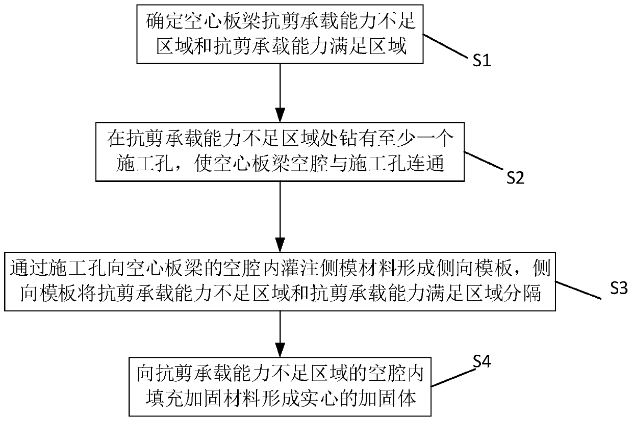
[0053] figure 1 It is a flow chart of the method for strengthening hollow slab beams provided by the present invention, such as figure 1 As shown, the method includes the following steps:

[0054] S1: Determine the area where the shear capacity of the hollow slab beam is insufficient and the area where the shear capacity is sufficient.

[0055] According to the bridge structure, design vehicle load and other parameters, the area with insufficient shear bearing capacity and the area with sufficient shear bearing capacity of the holl...

Embodiment 2

[0065] figure 2 It is a flow chart of the hollow slab beam strengthening method provided by the embodiment of the present invention, such as figure 2 As shown, this embodiment provides a method for strengthening hollow slab girders, which is mainly for the reinforcement of hollow slab girders that have been in service in bridges.

[0066] Compared with the first embodiment, the main steps of the method for strengthening the hollow slab girder in this embodiment are the same as those in the first embodiment, and only further specific limitations are made to step S2 in the first embodiment. This embodiment is mainly aimed at the specific description of the method for strengthening the hollow slab girder under the condition that the traffic on the bridge deck may be interrupted.

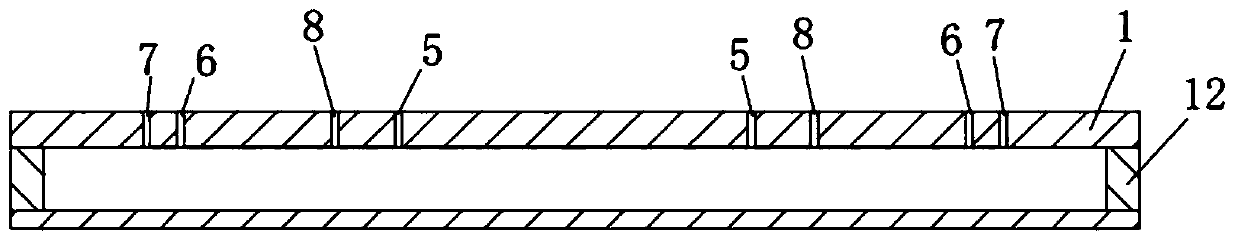
[0067] image 3 It is a schematic diagram of the structure after the construction hole is drilled for the hollow slab beam in this embodiment, Figure 4 It is a structural schematic diagram of the ...

Embodiment 3

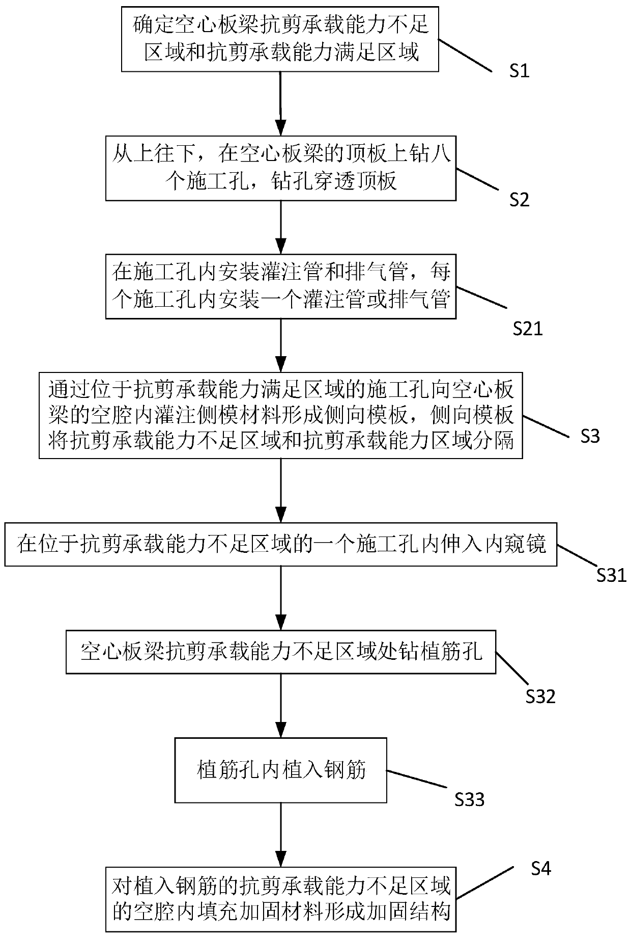
[0090] Figure 8 It is a flow chart of the hollow slab beam strengthening method provided by the embodiment of the present invention, such as Figure 8 As shown, this embodiment provides a method for strengthening hollow slab girders, which is mainly for the reinforcement of hollow slab girders that have been in service in bridges.

[0091] Compared with the second embodiment, the main steps of the method for strengthening the hollow slab girder in this embodiment are the same as those in the second embodiment, and only further specific limitations are made to step S2 in the first embodiment. This embodiment is mainly aimed at the specific description of the method for strengthening the hollow slab girder under the condition that the traffic on the bridge deck cannot be interrupted.

[0092] Figure 9 It is a schematic diagram of the structure after the construction hole is drilled for the hollow slab beam in this embodiment, Figure 10 It is a structural schematic diagram ...


PUM


Abstract

The invention relates to the technical field of bridge reinforcement, in particular to a hollow slab beam reinforcement method. The method comprises the following steps of S1, determining a shear bearing capacity insufficient area and a shear bearing capacity satisfaction area of the hollow slab beam; S2, drilling at least one construction hole in the shear bearing capacity insufficient area so that the cavity of the hollow slab girder is communicated with the construction holes; S3, pouring lateral framework materials into the cavity of the hollow slab beam through the construction holes to form a lateral formwork, wherein the lateral formwork separates the shear bearing capacity insufficient region from the shear bearing capacity satisfaction region; and S4, filling the cavity of the shear bearing capacity insufficient region with reinforcing materials to form a solid reinforcing body. Through the construction holes, it can be ensured that reinforcing materials enter the cavity, andthe lateral formworks can prevent the reinforcing materials from flowing from the shear bearing capacity insufficient area to the shear bearing capacity satisfaction area, so the using amount of the reinforcing materials is reduced, the maintenance and reinforcement cost is reduced, and the situation that the bearing capacity of the lower structure of the bridge is affected due to excessive increase of the dead weight of the hollow slab beam is avoided.

Description

technical field [0001] The invention relates to the technical field of bridge reinforcement, in particular to a method for reinforcing a hollow slab girder and a hollow slab girder. Background technique [0002] Prefabricated ordinary (or prestressed) concrete hollow slab girders are widely used in small and medium-span bridges due to the advantages of rapid factory manufacturing and simple process. Due to technical defects in materials, design, construction technology, etc., and the influence of factors such as overloaded vehicles during the operation period, some ordinary (or prestressed) concrete hollow slab beams in service in my country's early construction have oblique cracks and other shear loads at the ends. The problem of insufficient capacity. For such ordinary (or prestressed) concrete hollow slab girders, it is not only a waste of resources to directly dismantle and rebuild, but also requires interruption of traffic, high cost and long construction period. Espec...

Claims


Application Information

Patent Timeline
Patent Type & Authority Applications(China)
IPC IPC(8): E01D22/00
CPCE01D22/00
Inventor 刘其伟罗文林王成明
Owner 南京博瑞吉工程技术有限公司
Why Eureka
Try Eureka