
Method and device for controlling rotating speed of roller

A technology of drum speed and control method, which is applied in the directions of adaptive control, electric controller, general control system, etc., can solve the problems of inconstant drum speed, low control accuracy of agricultural machinery drum speed, and low control accuracy.

Inactive Publication Date: 2019-08-06
LOVOL HEAVY IND CO LTD
View PDF10 Cites 5 Cited by
  • Summary
  • Abstract
  • Description
  • Claims
  • Application Information

AI Technical Summary

Problems solved by technology

[0006] The purpose of the present invention is to provide a method for controlling the rotational speed of the drum, so as to solve the technical problems in the prior art that the rotational speed control accuracy of the agricultural machinery drum is not high and the rotational speed of the drum is not constant
[0007] The purpose of the present invention is also to provide a drum speed control device, the drum speed control device is used to solve the technical problem of low precision of the agricultural machine drum speed control

Method used


Image

  • Method and device for controlling rotating speed of roller
  • Method and device for controlling rotating speed of roller
  • Method and device for controlling rotating speed of roller

Examples


Embodiment 1

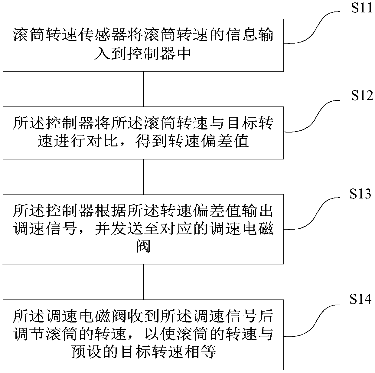
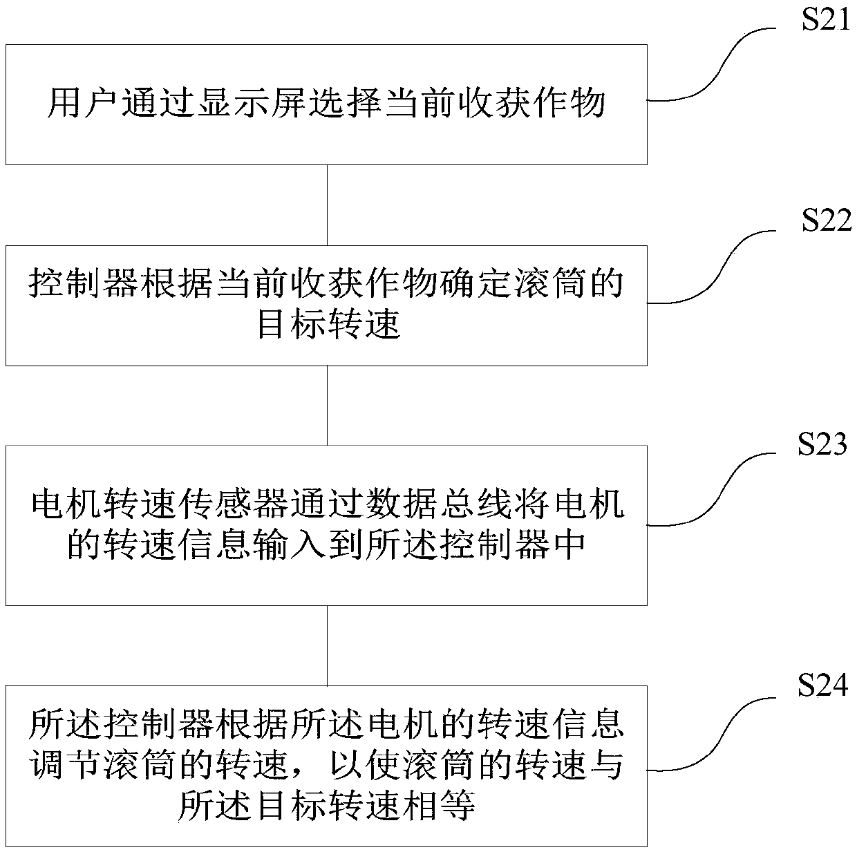
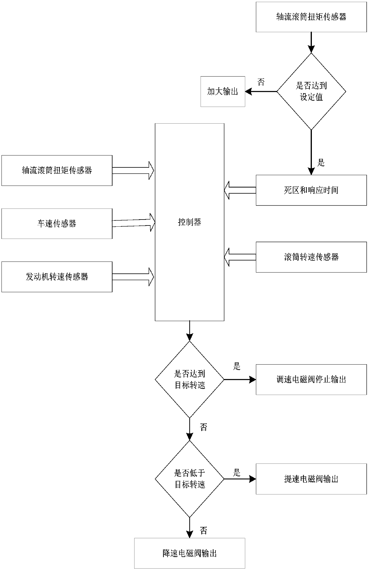
[0042] figure 1 It is a flow chart of the drum speed control method provided by the embodiment of the present invention; figure 2 It is a flow chart of the pre-steps of the drum speed control method provided by the embodiment of the present invention; image 3 It is a control logic flow chart of the method for controlling the rotational speed of the drum provided in the embodiment of the present invention.

[0043] like figure 1 As shown, in this embodiment, a drum speed control method is provided, and the drum speed control method includes the following steps:

[0044] Step S11, the drum speed sensor inputs the drum speed information into the controller;

[0045] Step S12, the controller compares the rotation speed of the drum with the target rotation speed to obtain a rotation speed deviation value;

[0046] Step S13, the controller outputs a speed regulation signal according to the speed deviation value, and sends it to the corresponding speed regulation solenoid valve...

Embodiment 2

[0070] Figure 4 It is a control principle block diagram of the drum rotation speed control device provided by the embodiment of the present invention. like Figure 4 As shown, this embodiment provides a drum speed control device, the drum speed control device includes a drum speed sensor, a speed regulating solenoid valve and a controller;

[0071] Both the drum speed sensor and the speed regulating solenoid valve are connected to the controller;

[0072] The drum speed sensor is used to input the information of the drum speed into the controller;

[0073] The controller is used to compare the rotation speed of the drum with the target rotation speed to obtain a rotation speed deviation value;

[0074] The controller is further configured to output a speed regulation signal according to the speed deviation value, and send it to a corresponding speed regulation solenoid valve;

[0075] The speed regulating solenoid valve is used to adjust the rotating speed of the drum aft...


PUM


Abstract

The invention provides a method and device for controlling the rotating speed of a roller, and relates to the technical field of agricultural machine control. The method for controlling the rotating speed of the roller comprises the steps that information of the rotating speed of the roller is input into a controller through a roller rotating speed sensor the controller compares the rotating speedof the roller with target rotating speed, and a rotating speed deviation value is obtained; the controller outputs a speed regulating signal according to the rotating speed deviation value, and sendsthe speed regulating signal to a corresponding speed regulating solenoid valve; after the speed regulating solenoid valve receives the speed regulating speed signal, the rotating speed of the rolleris regulated, so that the rotating speed of the roller is equal to the target rotating speed. According to the method and device, the technical problems that the rotating speed control precision of the roller of an agricultural machine is not high, and the rotating speed of the roller is not constant are solved.

Description

technical field [0001] The invention relates to the technical field of agricultural machinery control, in particular to a method and device for controlling the rotating speed of a drum. Background technique [0002] In recent years, the state has increased its support for agriculture in terms of policies, increased investment in the economy, and increased project support in terms of technology. In view of the support of national policies, land intensification has become more and more important in agricultural development, and land cultivation has gradually shifted from small workshops to industrial production. The intensification of land stimulates more young people to start farming, and at the same time, there is an increasing demand for the efficiency, economy and comfort of agricultural machinery. [0003] At present, the harvester is no longer just for a certain crop, but a real grain combine harvester, which can harvest corn, soybeans, rice, wheat, rapeseed, sunflower ...

Claims


Application Information

Patent Timeline
Patent Type & Authority Applications(China)
IPC IPC(8): A01D41/127G05B13/02G05B13/04G05B11/42
CPCA01D41/127G05B11/42G05B13/0265G05B13/042
Inventor 窦刚杨庚王进王德文柳汝桥李彦亭
Owner LOVOL HEAVY IND CO LTD
Learn More