Phase mask plate structure for simultaneous writing of multiple fiber gratings

A phase mask, simultaneous timing technology, applied in the directions of cladding fiber, optical waveguide light guide, light guide, etc., can solve the problems of laser ultraviolet beam energy waste, high fiber grating manufacturing cost, low production efficiency, etc., to avoid laser The effect of serious waste of beam energy, reduction of additional fiber positioning tooling, and improvement of energy rate

Pending Publication Date: 2019-08-02
FUZHOU PHOTOP QPTICS CO LTD
View PDF7 Cites 3 Cited by
  • Summary
  • Abstract
  • Description
  • Claims
  • Application Information

AI Technical Summary

Problems solved by technology

The traditional fiber grating manufacturing method can only produce and write a single fiber grating under each exposure of ultraviolet beams. While the production efficiency is low, the energy of the laser ultraviolet beam is greatly wasted, and the energy utilization rate is insufficient. For expensive lasers, the beam energy cannot be effectively used, which is undoubtedly the main reason for the high manufacturing cost of fiber gratings.
[0004] With the rapid development of fiber optic sensing and optical communication industries, especially the implementation of FTTH projects around the world, the demand for fiber gratings is increasing day by day, and then a large number of manual operations and low production efficiency make it difficult to adapt to the manufacturing cost. Large-volume, high-demand production and use, so reducing the production cost of fiber gratings has become an inevitable trend in future development

Method used


Image

  • Phase mask plate structure for simultaneous writing of multiple fiber gratings
  • Phase mask plate structure for simultaneous writing of multiple fiber gratings
  • Phase mask plate structure for simultaneous writing of multiple fiber gratings

Examples


Embodiment 1

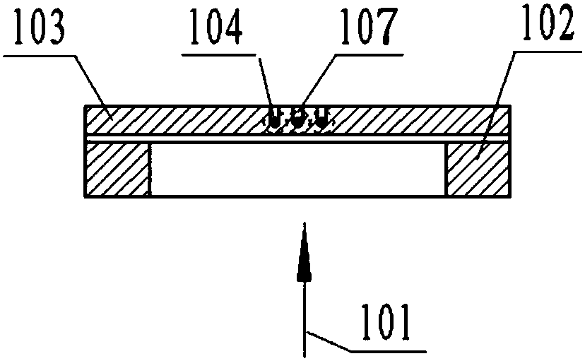
[0034] see figure 1 , 2 , the implementation steps of the present invention: several (this embodiment takes three as an example) bare optical fibers 104 are placed horizontally in the U-shaped positioning grooves on the non-grating side of the phase mask 103 in sequence, and the three optical fibers are positioned and positioned on the current phase mask. 103, and according to the U-shaped positioning groove structure processed on the non-grating side of the phase mask 103, the three optical fibers have the following arrangement characteristics: (1), the bare optical fiber 104 is positioned on the non-grating side of the phase mask 103 After the groove, the major optical fibers are evenly spaced; (2), the center distance between the bare optical fibers 104 is L, L≥D, and D is the diameter of the optical fiber in the coating area; (3), the optical fiber is located in the positioning groove Finally, the bare optical fiber 104 falls on the bottom of the positioning groove, and t...

Embodiment 2

[0036] Same as implementation case 1, for the difference, see image 3 , 4 : (1), the structure of the positioning groove on the non-grating side of the phase mask 103 is different, the U-shaped positioning groove of the optical fiber on the non-grating side of the phase mask 103 is changed to a V-shaped positioning groove, and the structure of the V-shaped positioning groove on the non-grating side of the phase mask 103 is obtained , multiple optical fibers fall on the bottom of the V-shaped groove for positioning; (2), the bottom of the V-shaped positioning groove cannot realize the function of converging the laser beam. Therefore, in this embodiment, a phase mirror 106 can be added in front of the phase mask 103 to realize the beam Convergence function, this kind of multi-fiber phase mask 103 structure, after positioning, the distance between the bare optical fibers 104 depends on the thickness of the phase mask 103 and the size of the top angle of the V-shaped groove, and ...


PUM


Abstract

The invention discloses a phase mask plate structure for simultaneous writing of multiple fiber gratings. A phase mask plate has a grating side and a non-grating side, multiple fiber positioning grooves are arranged at the non-grating side of the phase mask plate at intervals, multiple bare fibers are positioned in the positioning grooves of the non-grating side of the phase mask plate, and a plane in which the multiple bare fibers are is parallel to the phase mask plate. In the phase mask plate structure, fiber positioning grooves are uniformly distributed at the non-grating side of the phasemask plate, the fibers are distributed uniformly, and positioning groove depth is controlled, so that the multiple fibers are arranged in a near-field diffraction area of the phase mask plate and areexposed by ultraviolet beams, so as to carry out simultaneous writing of multiple fiber gratings. The method greatly improves production efficiency of fiber gratings, uses energy of ultraviolet beamseffectively, improves yield of fiber gratings, and lowers manufacture cost of fiber gratings.

Description

technical field [0001] The invention relates to the technical field of optical fiber grating writing, in particular to a phase mask structure for simultaneous writing of multiple optical fiber gratings. Background technique [0002] Fiber Bragg Grating (Fiber Bragg Grating, hereinafter referred to as FBG) is one of the most important photonic devices developed in the past half a century since the invention of optical fiber. Gratings, which can constitute many passive devices with unique properties, have been widely used in communication, sensing and other fields. [0003] The production technology of FBG directly determines the production efficiency of fiber gratings. At present, the commonly used large-scale fiber grating production technology is to use the phase mask method to make fiber gratings, which is based on the spatial interference generated by the near-field diffraction of the ultraviolet light source in the phase mask. The fringes create periodic changes in the ...

Claims


Application Information

Patent Timeline
Patent Type & Authority Applications(China)
IPC IPC(8): G02B6/02
CPCG02B6/02123G02B6/02142
Inventor 余忠伟林磊蔡光明郑彬
Owner FUZHOU PHOTOP QPTICS CO LTD
Why Eureka
Try Eureka