
Tunnel magnetoresistive accelerometer closed-loop control circuit based on feedback capacitance torquer

A closed-loop control circuit, tunnel magnetoresistance technology, applied in the direction of measurement of acceleration, speed/acceleration/shock measurement, testing/calibration of speed/acceleration/shock measurement equipment, etc. requirements, etc., to achieve the effect of good noise performance, high sensitivity, and increased detection sensitivity

Pending Publication Date: 2019-08-02
SOUTHEAST UNIV
View PDF0 Cites 3 Cited by
  • Summary
  • Abstract
  • Description
  • Claims
  • Application Information

AI Technical Summary

Problems solved by technology

[0003] At present, the measurement and control circuit of the tunnel magnetoresistive accelerometer adopts an open-loop detection method, which has problems such as low measurement accuracy and low sensitivity, which cannot meet the application requirements.

Method used


Image

  • Tunnel magnetoresistive accelerometer closed-loop control circuit based on feedback capacitance torquer
  • Tunnel magnetoresistive accelerometer closed-loop control circuit based on feedback capacitance torquer
  • Tunnel magnetoresistive accelerometer closed-loop control circuit based on feedback capacitance torquer

Examples


Embodiment 1

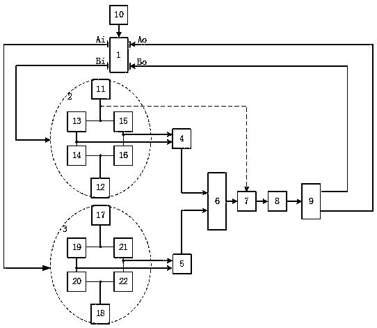
[0042] Such as Figure 4 -As shown in (A), when the first and second tunnel magnetoresistive sensor modules 2 and 3 use the first and second AC modulation signals 11 and 17, the system uses the AC demodulation filter circuit 7, and the AC demodulation filter circuit 7 It includes a comparator 29 , a multiplier 30 and a low-pass filter 31 . The output of the third instrument amplifying circuit 6 and the first AC modulation signal 11 of the first tunnel magnetoresistive sensing module 2 are connected to the two inputs of the AC demodulation filter circuit (7), and the first stream modulation signal 11 is connected to the comparator 29 The input of the third instrument amplifying circuit 6 is connected with the input of the multiplier 30; the output of the comparator and the output of the third instrument amplifying circuit 6 are jointly used as the input of the multiplier 30, and the multiplier 30 realizes the AC solution Adjust the rectification of the input signal of the filt...

Embodiment 2

[0044] Such as Figure 4 - As shown in (B), when the first and second tunnel magnetoresistive sensor modules 2 and 3 use the first and second reference sources 11 and 17, the system uses a DC filter circuit 7. The output of the third instrument amplifier circuit 6 is connected to the input of the DC filter circuit (7), the DC filter circuit 7 mainly removes the AC noise interference in the output signal of the third instrument amplifier circuit 6, and the output of the DC filter circuit 7 is connected to the PID control circuit The input of 8 is connected as the input control signal of PID control circuit 8.

[0045] Such as Figure 5 As shown, the PID control circuit 8 mainly includes a reference voltage 32 , a subtraction circuit 33 , a proportional link 34 , an integral link 35 , a differential link 36 and an accumulation circuit 34 . Wherein, the output of the AC demodulation filter circuit / DC filter circuit 7 is used as the input of the PID control circuit, and the erro...


PUM


Abstract

The invention discloses a tunnel magnetoresistive accelerometer closed-loop control circuit based on a feedback capacitance torquer. The closed-loop control circuit comprises a tunnel magnetoresistiveaccelerometer structure, a tunnel magnetoresistive sensor module, an instrument amplifier circuit, a demodulation filter circuit, a PID control circuit, a feedback force application circuit and an acceleration signal. The tunnel magnetoresistive accelerometer has the advantages of high sensitivity and good noise performance; the tunnel magnetoresistive sensor module adopts a push-pull bridge structure, and can increase detection sensitivity of the tunnel magnetoresistive sensor and suppress common-mode interference in the signal; meanwhile, the tunnel magnetoresistive sensor module adopts anAC modulation working mode and can eliminate interference of a magnetic field in the space; the PID control circuit is used to track error signals until the error signals disappear, and correction ofthe closed-loop system can be realized quickly; and feedback force correction is realized through a differential capacitance torquer, and an inertial mass block can be restrained near the central position, thereby realizing closed-loop control of the tunnel magnetoresistive accelerometer and increasing system stability.

Description

technical field [0001] The invention relates to micro-electromechanical system (MEMS) and micro-inertial device measurement technology, in particular to a closed-loop control circuit of a tunnel reluctance accelerometer based on a feedback capacitive torque device. Background technique [0002] Tunnel magnetoresistance accelerometer refers to a new type of accelerometer based on tunnel magnetoresistance effect. The tunnel magnetoresistance effect mainly refers to the magnetic tunnel junction composed of two layers of ferromagnetic metals and an intermediate insulating layer. If the polarization directions of the two layers of ferromagnetic metals are parallel or the tunnel gap becomes smaller, the possibility of electrons tunneling through the insulating layer will decrease. becomes larger, the magnetic tunnel junction exhibits a very small resistance macroscopically; if the polarization direction is antiparallel or the tunnel gap becomes larger, the possibility of electron ...

Claims


Application Information

Patent Timeline
Patent Type & Authority Applications(China)
IPC IPC(8): G01P15/105G01P21/00
CPCG01P15/105G01P21/00
Inventor 杨波张婷梁卓玥王斌龙
Owner SOUTHEAST UNIV
Learn More