Quick connector structure

A joint structure and fast technology, applied in the direction of pipe joints, pipes/pipe joints/pipe fittings, pipe components, etc., can solve problems such as difficulties, inconvenient installation of pipes, inconvenient use of space problems and tools.

Inactive Publication Date: 2019-08-02
SHOWER KAOKANG ENTERPRISE +1
View PDF7 Cites 0 Cited by
  • Summary
  • Abstract
  • Description
  • Claims
  • Application Information

AI Technical Summary

Problems solved by technology

[0002] According to the currently known first and second usage status of the pipeline joints, the reference pictures are as follows: Image 6 , 7 As shown, the tube body 40 is directly sleeved and combined with the pipeline joint 50. In order to prevent the tube body 40 from falling out of the sleeved pipeline joint 50, the adjustable tube bundle device 60 will be locked or clamped. When the pipes are connected, a bundle of pipe devices 60 needs to be installed at each joint, which makes it inconvenient to install the pipes, and the installation positions of the pipes are usually in small spaces or hidden locations. After the tube body 40 is fitted with the pipeline connector 50, it is extremely difficult to adjust the binding tube device 60, and it is also inconvenient to use tools due to space constraints, so there is a need for improvement

Method used


Image

  • Quick connector structure
  • Quick connector structure
  • Quick connector structure

Examples


Embodiment Construction

[0014] In order to further understand the structure, characteristics and other purposes of the present invention, the following preferred embodiments are attached to the accompanying drawings for detailed description as follows, but the embodiments described in the illustrations are for illustration purposes, not for patent application. the only limitation.

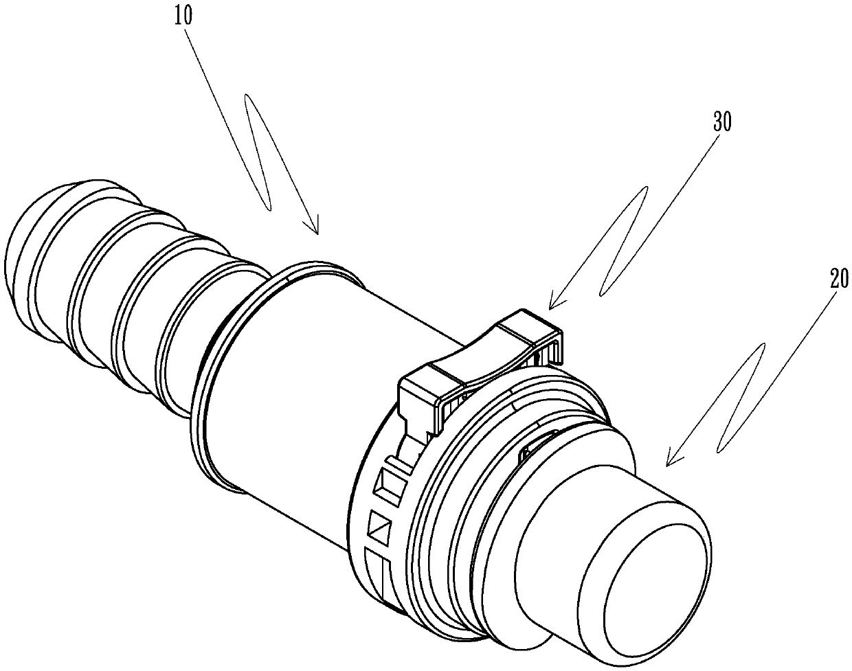
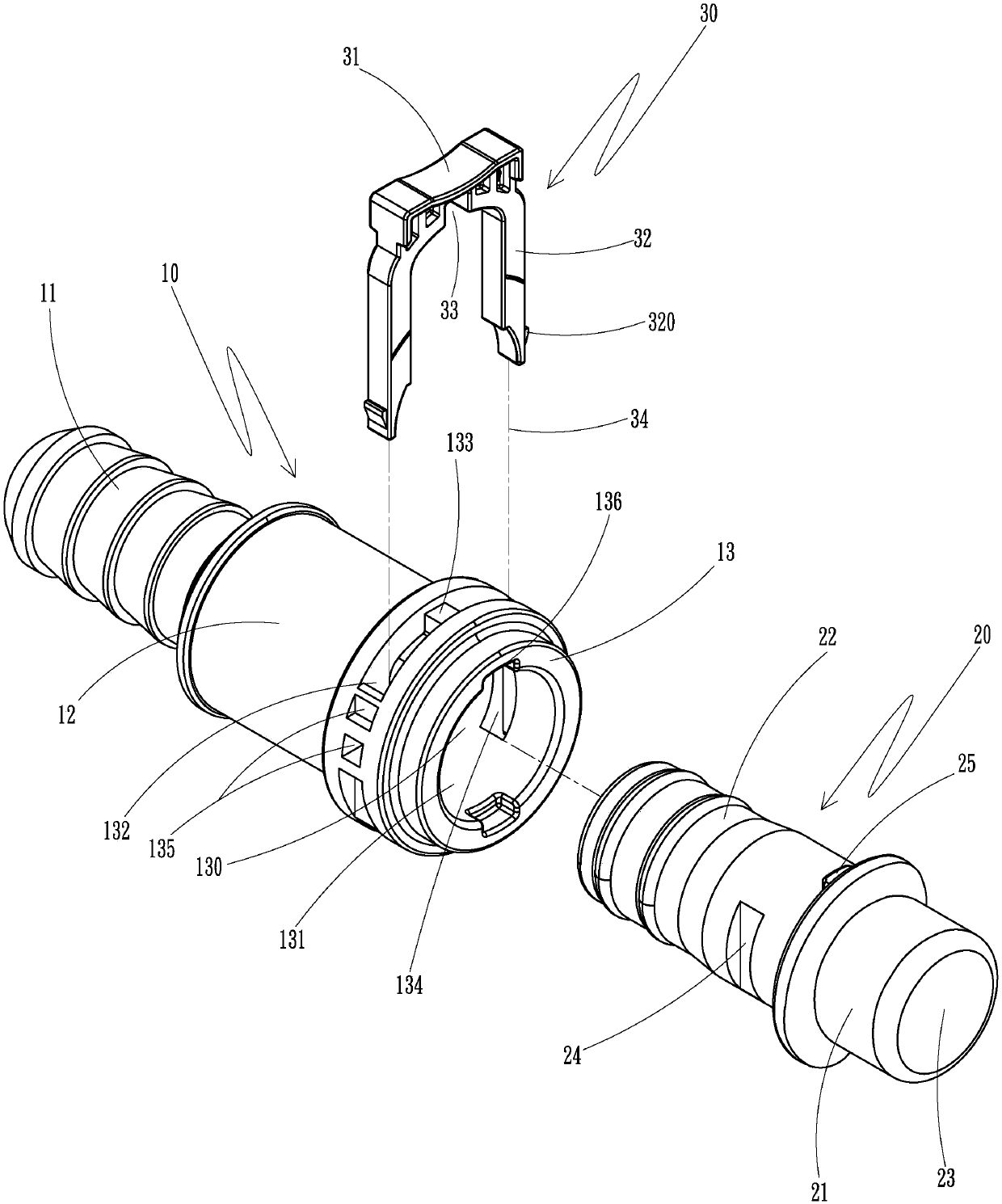
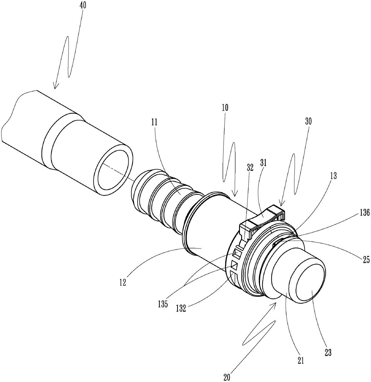
[0015] Please refer to figure 1 , figure 2 As shown, it is a schematic diagram of a three-dimensional combination state and a three-dimensional decomposition state of the quick joint structure of the present invention, which includes:

[0016] A set of joint body 10, the joint body 10 is a pipe joint, a three-way valve joint or a washing machine valve joint, etc., and the joint body 10 is provided with a joint part 11, a joint body part 12 and a joint part 13, The fitting part 13 is provided with a fitting hole 130 through the joint part 11 and the fitting body part 12, and the fitting hole 130 is provided with a hole...


PUM


Abstract

The invention relates to a quick connector structure including a fitting connector, a connector, and a U-shaped positioning snap pin. The fitting connector is a pipe connector, a three-way valve connector, or a washing machine valve connector. The fitting connector is combined with a pipe body. The U-shaped positioning snap pin ensures the stability of the connection between the fitting connectorand the connector. The quick connector structure enables rapid positioning and assembly, reducing the assembly difficulty in a smaller or concealed space and achieving the effects of assembly stability and convenience.

Description

technical field [0001] The invention relates to a quick joint structure, especially to a technical field applied to pipeline joint structures. Background technique [0002] According to the currently known first and second usage status of the pipeline joints, the reference pictures are as follows: Image 6 , 7 As shown, the pipe body 40 is directly sleeved and combined with the pipe joint 50. In order to prevent the pipe body 40 from breaking away from the sleeved pipe joint 50, the adjustable pipe bundle device 60 will be locked or clamped. When the pipes are connected, a bundle of pipe devices 60 needs to be installed at each socket, which makes it inconvenient to install the pipes, and the installation positions of the pipes are usually in small spaces or hidden locations. After the tube body 40 and the pipeline connector 50 are fit together, it is extremely difficult to adjust and tighten the tube binding device 60 , and the use of tools is also inconvenient due to spac...

Claims


Application Information

Patent Timeline
Patent Type & Authority Applications(China)
IPC IPC(8): F16L37/12
CPCF16L37/1225F16L37/144F16K11/22F16L2201/10F16L41/021
Inventor 陈昭圻江盛恩
Owner SHOWER KAOKANG ENTERPRISE
Why Eureka
Try Eureka