Inward reducing die

A mold and necking technology, which is applied in the direction of forming tools, manufacturing tools, metal processing equipment, etc., can solve the problems of long production time, reduced product service life, and easy wrinkle or breakage on the shrinking mold surface, so as to improve the thickness , Improve the effect of structural strength

Inactive Publication Date: 2019-08-02
远军热能动力科技有限公司
View PDF0 Cites 1 Cited by
  • Summary
  • Abstract
  • Description
  • Claims
  • Application Information

AI Technical Summary

Problems solved by technology

In the pipe shrinking process, the shrinkage of the pipe diameter is realized through the mutual extrusion and cooperation of the upper shrinking die and the lower shrinking die. During the use of the existing shrinking die, it is necessary to press the product into the die, turn over the die, and block Extruded products have disadvantages such as long production time, low production efficiency, high manufacturing cost, and complicated operation; The tube is easy to bulge (form wings) at the junction of the upper necking die and the lower necking die, which will affect the product quality and even cause the product to be scrapped
[0003] The shrinking mold bears the corresponding reaction force during the deformation process. Since the shrinking mold is an integral design, the surface stress concentration of the shrinking mold cannot be released, and the surface of the shrinking mold is prone to wrinkles or broken, which greatly reduces the use of the shrinking mold Life, increase production cost, affect production efficiency and product quality
[0004] However, there is no relevant technology for the necking of pipes, steel cylinders, and tanks, especially the necking of inward flanging. The products formed by the above-mentioned processing methods are likely to break the necking, or the properties of the material will change after extrusion. Thereby reducing the service life of the product, which urgently needs to be solved, so the inner flanging mold is the key

Method used


Image

  • Inward reducing die
  • Inward reducing die

Examples


Embodiment Construction

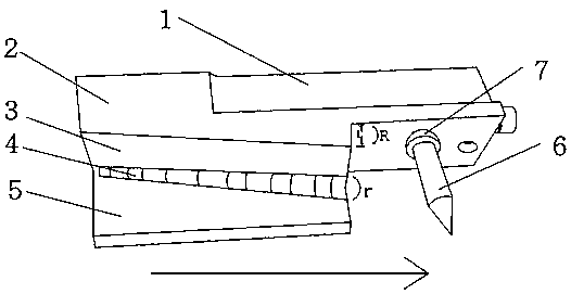
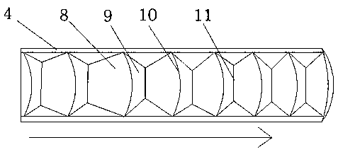
[0021] As shown in the accompanying drawings: a kind of inner necking mold, including a mold body 2 and a necking part for inner flanging extrusion, the mold body 2 is provided with an installation part 1, and the installation part 1 is used to place the inner necking mold Installed on a lathe, the necking part includes a transverse part 5, a longitudinal part 3 and an arc part 4, the longitudinal part 3 is located on the upper end surface of the transverse part 5, the arc part 4 is located between the longitudinal part 3 and the transverse part 5, and the mold body 2. The right end is provided with a through-hole cutter 6, and the front end of the through-hole cutter 6 is conical, which is convenient for carrying out the through-hole operation to the workpiece pipe.

[0022] A reinforcing part 7 is provided between the through-hole knife 6 and the mold body 2 , and the setting of the reinforcing part 7 is convenient for improving the connection strength between the through-hol...


PUM


Abstract

The invention provides an inward reducing die. The inward reducing die comprises a die body and a reducing part, wherein the reducing part is used for flanging and compressing inwards, and a mountingpart is arranged on the die body. The inward reducing die is characterized in that the reducing part comprises a transverse part, a longitudinal part and an arc part, the longitudinal part is locatedon the upper end surface of the transverse part, the arc part is located between the longitudinal part and the transverse part, a drilling knife is arranged on the right end of the die body, and the front end of the drilling knife is conical. When a pipe or workpiece is processed, the inward flanging of the pipe is effectively realized by the reducing part, the technical problem of observation ofthe inward flanging is effectively solved, additionally, the reducing end is thickened, and the structural strength of the reducing end is effectively increased. The drilling knife is arranged, so that the pipe is drilled and shaped after the processing is completed, additionally, the reducing end is thickened under the squeezing action of the drilling knife, the material of the pipe is compact after being heated, and the reducing quality is increased.

Description

technical field [0001] The invention relates to the technical field of necking processing, in particular to an inner necking die. Background technique [0002] As we all know, for example, for pipe fittings used in pipelines of automobiles and air conditioners, the ends of the pipes must be formed through expanding or shrinking processes. In the pipe shrinking process, the shrinkage of the pipe diameter is realized through the mutual extrusion and cooperation of the upper shrinking die and the lower shrinking die. During the use of the existing shrinking die, it is necessary to press the product into the die, turn over the die, and block Extruded products have disadvantages such as long production time, low production efficiency, high manufacturing cost, and complicated operation; The tube is easy to bulge (form wings) at the junction of the upper necking die and the lower necking die, which will affect the product quality and even cause the product to be scrapped. [0003...

Claims


Application Information

Patent Timeline
Patent Type & Authority Applications(China)
IPC IPC(8): B21D37/10B21D19/10B21D41/04
CPCB21D19/10B21D37/10B21D41/04
Inventor 郭远军郭玉君
Owner 远军热能动力科技有限公司
Why Eureka
Try Eureka