
Device and method for measuring superconducting transient electromagnetic signals

A technology of transient electromagnetics and measuring devices, which is applied in measuring devices, electric/magnetic exploration, radio wave measurement systems, etc., can solve problems such as interference signals in the secondary eddy current field measurement process, and achieve the effect of accurate measurement

Active Publication Date: 2020-08-28
SHANGHAI INST OF MICROSYSTEM & INFORMATION TECH CHINESE ACAD OF SCI
View PDF8 Cites 0 Cited by
  • Summary
  • Abstract
  • Description
  • Claims
  • Application Information

AI Technical Summary

Problems solved by technology

[0004] In view of the shortcomings of the prior art described above, the purpose of the present invention is to provide a measurement device and method for superconducting transient electromagnetic signals, which are used to solve the problem of interference signals in the measurement process of the existing secondary eddy current field

Method used

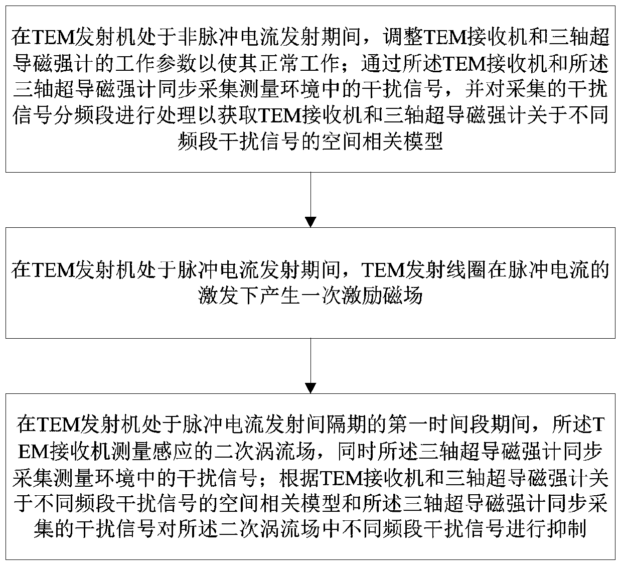

Image

  • Device and method for measuring superconducting transient electromagnetic signals
  • Device and method for measuring superconducting transient electromagnetic signals
  • Device and method for measuring superconducting transient electromagnetic signals

Examples


Embodiment 1

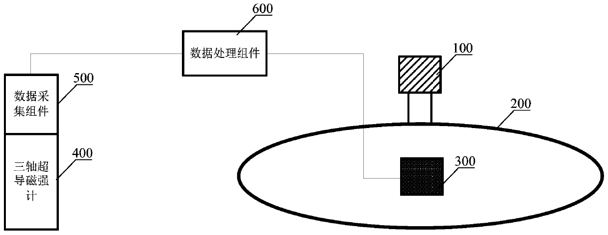
[0061] like figure 1 As shown, the present embodiment provides a measurement device for superconducting transient electromagnetic signals, and the measurement device includes:

[0062] TEM transmitter 100, for transmitting pulsed current;

[0063] The TEM transmitting coil 200 is electrically connected to the TEM transmitter 100, and is used to generate an excitation magnetic field under the excitation of the pulse current;

[0064] TEM receiver 300, is arranged in described TEM transmission coil 200, is used for during described TEM transmitter 100 is in the period of non-pulse current transmission, collects the interference signal in the measurement environment; When described TEM transmitter 100 is in pulse current transmission measuring the induced secondary eddy current field during a first time period of the interval;

[0065] The three-axis superconducting magnetometer 400 is arranged outside the TEM transmitting coil 200 and has a preset distance from the TEM receive...

Embodiment 2

[0092] like Figure 4 As shown, the present embodiment provides a measurement device for superconducting transient electromagnetic signals. On the basis of Embodiment 1, the measurement device further includes:

[0093] A magnetic sensor (not shown in the figure) is set at the TEM receiver 300, and is used to collect the TEM transmitting coil 200 under the excitation of a single-cycle pulse current when the TEM transmitter 100 is in the period of pulse current transmission. The primary reference magnetic field generated at the TEM receiver 300;

[0094] The driving source 700 is electrically connected to the magnetic sensor, and is used to select an effective magnetic field interval from the primary reference magnetic field, and reverse it to obtain a canceling magnetic field, and then according to the size of the canceling magnetic field and the concentric coil 800 The number of turns generates a drive current;

[0095] The concentric coil 800 is electrically connected to t...


PUM


Abstract

The invention provides a measuring device and method of a superconducting transient electromagnetic signal. The measuring device comprises a TEM transmitter, a TEM transmitting coil, a TEM receiver, athree-axis superconducting magnetometer, a data collection assembly and a data processing assembly, wherein the TEM transmitting coil is electrically connected with the TEM transmitter, the TEM receiver is arranged in the TEM transmitting coil, the three-axis superconducting magnetometer is arranged outside the TEM transmitting coil and with preset spacing between the TEM receiver, the data collection assembly is electrically connected with the three-axis superconducting magnetometer, and the data processing assembly is in data communication with the TEM receiver and the data collection assembly. According to the measuring device, the problem that interference signals exist in the measuring process of the existing secondary eddy current field, and thus inaccurate measurement of the secondary eddy current field is solved.

Description

technical field [0001] The invention belongs to the field of magnetic measurement, in particular to a measurement device and method for superconducting transient electromagnetic signals. Background technique [0002] Transient electromagnetic method (Time domain electromagnetic methods, TEM), also known as time domain electromagnetic method, is to use ungrounded return line or grounding line source to transmit an excitation magnetic field underground, and use a coil or ground electrode to observe two The method of the sub-eddy current field; simply put, the basic principle of the transient electromagnetic method is the law of electromagnetic induction. The attenuation process is generally divided into early, middle and late stages; the early electromagnetic field is equivalent to the high-frequency components in the frequency domain, with fast attenuation and small skin depth; while the late electromagnetic field is equivalent to the low-frequency components in the frequency...

Claims


Application Information

Patent Timeline
Patent Type & Authority Patents(China)
IPC IPC(8): G01V3/10
CPCG01V3/10
Inventor 伍俊荣亮亮裴易峰邱隆清李兆宇谢晓明
Owner SHANGHAI INST OF MICROSYSTEM & INFORMATION TECH CHINESE ACAD OF SCI
Learn More