


Quick Research
Generate reliable direction feasibility study reports for your R&D in just a few steps.

Technical Q&A
Discover and master advanced knowledge NOW. Basics, ideas, possibilities, all at once.

Find Solutions
As an expert in R&D theories, this can generate solutions to your technical problems instantly.

Evaluate Feasibility
Analyze your overall solution with one click, know your potential R&D risks in advance.

Monitor Landscape
Get weekly tech updates, stay abreast of the latest tech innovations and key insights.
Resistance-type perpendicular shaft wind turbine and working method thereof
A vertical axis and wind turbine technology, applied to wind engines at right angles to the wind direction, combination of wind engines and wind motors, etc., can solve the problem that resistance generators cannot have constant output power, equipment safety cannot be guaranteed, speed and torque Small problems, to achieve stable power generation, avoid equipment damage, and ensure output power
- Summary
- Abstract
- Description
- Claims
- Application Information
AI Technical Summary
Problems solved by technology
Method used
Image

Examples
Embodiment 2
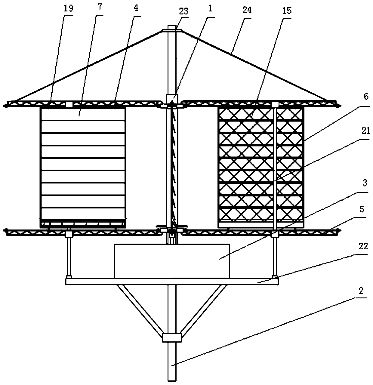
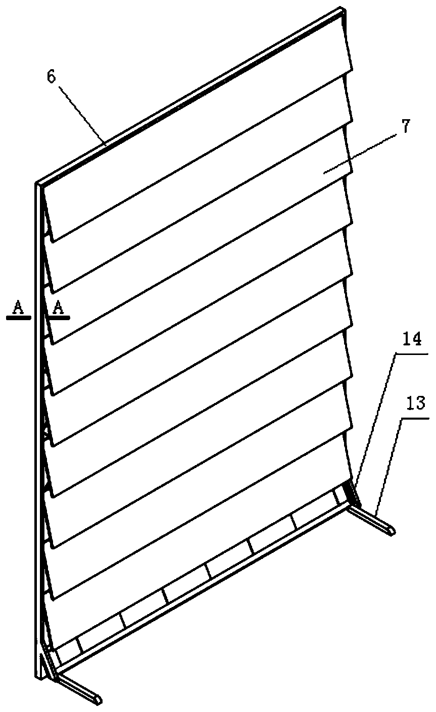
[0051] This embodiment discloses a working method of a drag-type vertical axis wind turbine: when the unidirectional wind acts on the fan blades arranged in pairs, one of the fan blades in the fan blades arranged in pairs will When the rotating shaft rotates, a gap for wind flow is formed between adjacent wind choke plates, and the wind choke plate of the other fan blade is attached to the mesh limit structure under the action of wind force. At this time, the wind force acting on the two blades forms a pressure difference , Under the action of the pressure difference, the fan blades drive the rotor to rotate, and the rotation of the rotor drives the generator to generate electricity.
[0052] Using this power generation method, compared with the traditional drag-type wind generator, it can form a higher rotational moment, and the power generation efficiency is high.
Embodiment 3
[0054] This embodiment discloses a working method of a resistance type vertical axis wind turbine: the speed sensor collects the speed information of the drum in real time and transmits it to the controller. When the wind speed changes, the controller receives the wind speed change signal transmitted by the speed sensor , to control the operation of the first motor, the drive belt drives the fan blades to move along the cantilever frame mechanism, changing the distance between the fan blades and the rotation, so that the rotation speed of the drum returns to the set value again, so that the generator outputs electric energy according to the set power.
Embodiment 4
[0056] This embodiment discloses a braking method for a resistance-type vertical axis wind turbine: the second motor operates, the connecting belt is released, and the wind choke plate slides down along the T-shaped slot under the action of gravity and is stacked on the receiving rod. At this time, the fan The stressed area of the leaf is greatly reduced, the rotating speed is gradually reduced, and braking is realized.
PUM
 Abstract
Description
Claims
Application Information
 - R&D Engineer
- R&D Manager
- IP Professional
- Industry Leading Data Capabilities
- Powerful AI technology
- Patent DNA Extraction
Browse by: Latest US Patents, China's latest patents, Technical Efficacy Thesaurus, Application Domain, Technology Topic, Popular Technical Reports.
© 2024 PatSnap. All rights reserved.Legal|Privacy policy|Modern Slavery Act Transparency Statement|Sitemap|About US| Contact US: help@patsnap.com