A method and device for quantitative detection of defects in moving metal components

A quantitative detection method and technology for metal components, applied in the direction of material magnetic variables, etc., can solve problems such as inability to realize quantitative identification of defects, blind spots on surface and sub-surface cracks, and detection speed limitations, so as to improve quality monitoring capabilities and improve market competition. power and huge economic benefits

Active Publication Date: 2021-05-25
UNIV OF ELECTRONICS SCI & TECH OF CHINA
View PDF6 Cites 0 Cited by
  • Summary
  • Abstract
  • Description
  • Claims
  • Application Information

AI Technical Summary

Problems solved by technology

[0009] The purpose of the present invention is: in order to solve the problem that existing defect detection methods for moving metal components have blind spots for surface and sub-surface cracks, cannot realize quantitative defect identification or can realize quantitative defect identification, but the detection speed is limited, etc. The invention proposes a defect quantitative detection method and device of a moving metal component, which effectively improves the sensitivity and signal strength of the defect detection of the moving metal component, and realizes the rapid quantitative identification of the defect of the moving metal component

Method used


Image

  • A method and device for quantitative detection of defects in moving metal components
  • A method and device for quantitative detection of defects in moving metal components
  • A method and device for quantitative detection of defects in moving metal components

Examples


Embodiment Construction

[0051] In order to make the object, technical solution and advantages of the present invention clearer, the present invention will be further described in detail below in conjunction with the accompanying drawings and embodiments. It should be understood that the specific embodiments described here are only used to explain the present invention, not to limit the present invention.

[0052] figure 1 It is a schematic flow chart of a defect quantitative detection method for a moving metal component of the present invention; a quantitative defect detection method for a moving metal component comprises the following steps:

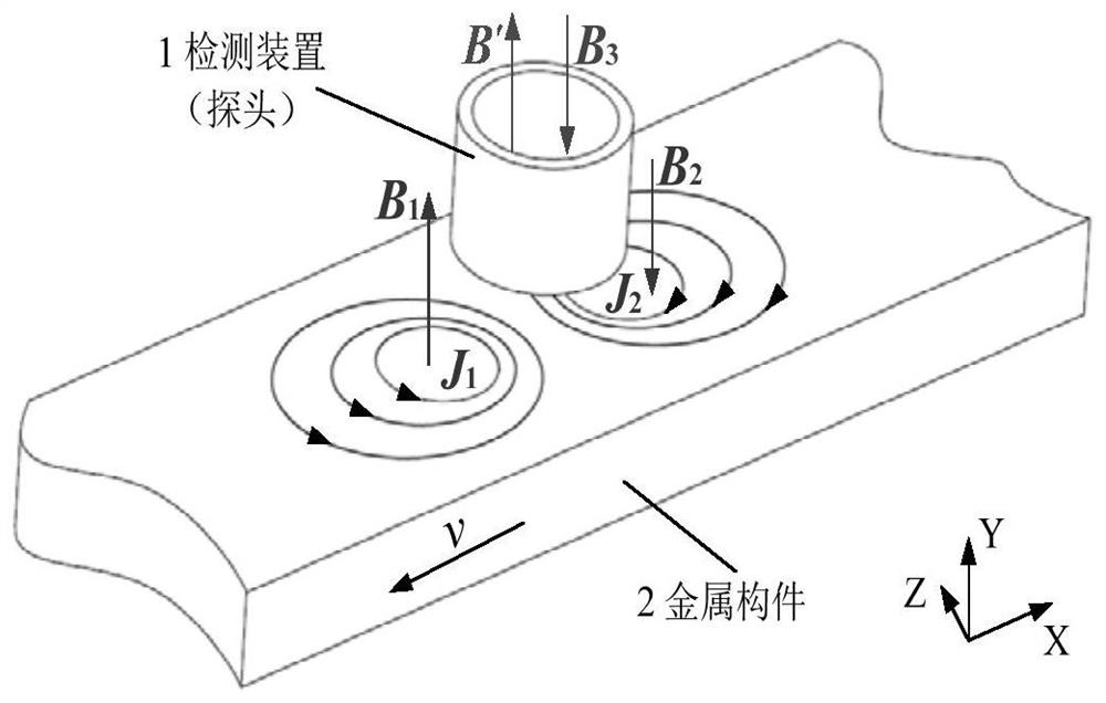
[0053] S1. Fix the detection probe above the moving metal component, and pass direct current into the excitation coil of the detection probe to generate a constant magnetic field;

[0054] S2. Determine the installation position of the magnetic sensor, and use the magnetic sensor to collect the magnetic induction intensity signal of the magnetic field in step...


PUM


Abstract

The invention discloses a defect quantitative detection method and device of a moving metal component. The method includes fixing a detection probe to generate a constant magnetic field, setting the position of a magnetic sensor and collecting a magnetic induction intensity signal, performing amplification and filtering processing on the magnetic induction intensity signal, and converting the response signal The peak value and the baseline value are differentially processed to obtain the differential peak value, and the inversion model of the defect parameter of the moving metal component is constructed to calculate the defect parameter; the device includes an excitation signal generation module, a signal amplification and filtering module, a data acquisition and processing module and a defect parameter calculation module . The invention realizes quantitative detection of defects in moving metal components by using the moving eddy current generated by the relative motion between the detection device and the metal component to be tested, improves the ability to monitor the quality of metal parts, and improves the market competitiveness of such metal parts, thereby bringing to huge economic and social benefits.

Description

technical field [0001] The invention belongs to the technical field of defect detection of metal components, and in particular relates to a defect quantitative detection method and device of a moving metal component. Background technique [0002] Non-destructive testing (NDT, Nondestructive Testing) technology refers to the internal and surface structure, nature, state and Effective detection of physical properties such as defects. As a branch of nondestructive testing, electromagnetic nondestructive testing technology detects defects in materials through changes in the electromagnetic properties of materials, making this testing method widely used in transportation such as aircraft fuselage structures, steam pipelines, and oil and natural gas. Production quality monitoring and online health status detection of metal components such as pipelines and railway rails. Electromagnetic nondestructive testing methods mainly include: eddy current testing, magnetic flux leakage tes...

Claims


Application Information

Patent Timeline
Patent Type & Authority Patents(China)
IPC IPC(8): G01N27/85G01N27/90
CPCG01N27/85G01N27/90
Inventor 于亚婷袁飞刘博文李林峰
Owner UNIV OF ELECTRONICS SCI & TECH OF CHINA
Why Eureka
Try Eureka