
Novel carbon fiber prepreg system and manufacturing method of novel carbon fiber prepreg

A carbon fiber prepreg, carbon fiber tow technology, applied in chemical instruments and methods, lamination auxiliary operations, injection devices, etc., can solve the problems of reduced precision, inability to achieve double-sided coating, poor infiltration effect, etc. Progress, reduce the weight of sprayed resin, good infiltration effect

Pending Publication Date: 2019-07-26
汉硕高新材料(天津)有限公司
View PDF0 Cites 0 Cited by
  • Summary
  • Abstract
  • Description
  • Claims
  • Application Information

AI Technical Summary

Problems solved by technology

[0003] 1. In this way, generally 1m 2 Only 7-8g of resin glue can be laid on the release paper, and the thickness is about 1um, so the gap between the upper and lower two hot pressing rollers is required to be about 1um, which requires relatively high precision. If it is carbon fiber tow It is difficult to achieve when the resin is thin or the weight of the resin is less; and if some heterogeneous substances are added to the resin glue, it is easy to damage the surface of the roller for a long time, so that the gap between the upper and lower rollers increases. , thereby reducing the accuracy;
[0004] 2. If the prepreg is used in high-end fields, such as aviation, the less the resin is required, the better, and the content should be around 30%, which has a relatively high modulus. For particularly thin carbon fiber tow For example, for 20g of fiber, the corresponding resin weight is required to be around 10g. The existing device cannot achieve double-sided coating, only 10g on one side, and the wetting effect is poor.

Method used

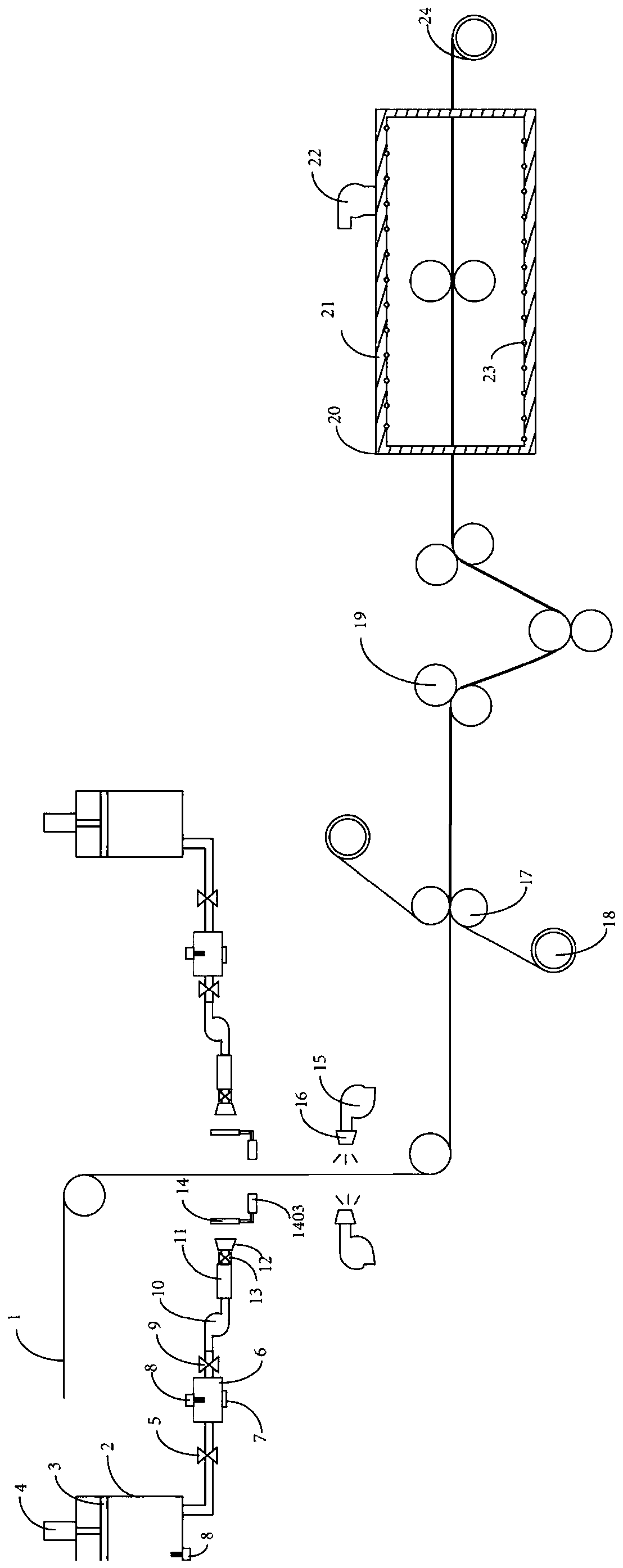
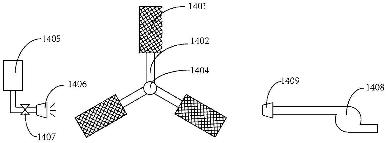
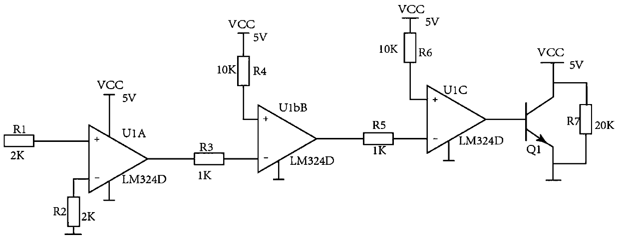

Image

  • Novel carbon fiber prepreg system and manufacturing method of novel carbon fiber prepreg
  • Novel carbon fiber prepreg system and manufacturing method of novel carbon fiber prepreg
  • Novel carbon fiber prepreg system and manufacturing method of novel carbon fiber prepreg

Examples


Embodiment Construction

[0039] The technical solutions of the present invention will be clearly and completely described below in conjunction with the accompanying drawings. Apparently, the described embodiments are some of the embodiments of the present invention, but not all of them. Based on the embodiments of the present invention, all other embodiments obtained by persons of ordinary skill in the art without making creative efforts belong to the protection scope of the present invention.

[0040] In the description of the present invention, it should be noted that the terms "center", "upper", "lower", "left", "right", "vertical", "horizontal", "inner", "outer" etc. The indicated orientation or positional relationship is based on the orientation or positional relationship shown in the drawings, and is only for the convenience of describing the present invention and simplifying the description, rather than indicating or implying that the referred device or element must have a specific orientation, ...


PUM


Abstract

The invention provides a novel carbon fiber prepreg system and a manufacturing method of novel carbon fiber prepreg. The novel carbon fiber prepreg system comprises high-pressure resin nozzles, wherein the high-pressure resin nozzles are symmetrically arranged on the front side and the back side of a carbon fiber bundle, one ends of the high-pressure resin nozzles are connected with a metering device, one end of the metering device is connected with a stock bin, the stock bin communicates with the metering device and the high-pressure resin nozzles in sequence, a first electromagnetic valve isarranged between the stock bin and the metering device, a second electromagnetic valve is arranged between the metering device and the high-pressure resin nozzles, a heating mechanism is further arranged in the metering device, and an adhesive amount adjusting device is further arranged between the high-pressure resin nozzles and the carbon fiber bundle, and is used for adjusting the amount of adhesives sprayed onto the carbon fiber bundle by the high-pressure resin nozzles. According to the novel carbon fiber prepreg system and the manufacturing method of novel carbon fiber prepreg, a two-side spraying structure is adopted for resin infiltration on the carbon fiber bundle, so that the infiltration effect is good.

Description

technical field [0001] The invention relates to the technical field of carbon fiber, in particular to a novel carbon fiber prepreg system and a manufacturing method thereof. Background technique [0002] At present, the method of impregnating carbon fiber tow with resin glue in the prior art is generally by coating resin glue on the release paper, then hot pressing the release paper on the carbon fiber tow, and then tearing the release paper The resin glue is impregnated on the carbon fiber tow by means, but the structure and method of such prepreg have the following problems: [0003] 1. In this way, generally 1m 2 Only 7-8g of resin glue can be laid on the release paper, and the thickness is about 1um, so the gap between the upper and lower two hot pressing rollers is required to be about 1um, which requires relatively high precision. If it is carbon fiber tow It is difficult to achieve when the resin is thin or the weight of the resin is less; and if some heterogeneous ...

Claims


Application Information

Patent Timeline
IPC IPC(8): B05B16/20B05B13/02B05B15/555B05B12/08B05B9/04B05B9/00B05B1/28B32B37/06B32B37/08B32B37/10B32B38/10
CPCB05B16/20B05B13/0278B05B12/081B05B9/002B05B9/0413B05B15/555B05B1/28B32B37/10B32B37/06B32B37/08B32B38/10
Inventor 周易辛媛
Owner 汉硕高新材料(天津)有限公司
Learn More