
Intelligent monitoring and identifying system of box body

A technology of intelligent monitoring and identification system, which is applied in the direction of control/regulation system, temperature control, non-electric variable control, etc. It can solve the problems of real-time monitoring of the internal working conditions of the pry body, affecting the normal operation of the internal equipment of the pry body, and being unable to know in time Fault conditions and other problems, to achieve the effect of strengthening anti-theft function, efficient anti-theft, and ensuring safe use

Pending Publication Date: 2019-07-23
SHANGHAI BAOLIN ELECTRIC GRP
View PDF1 Cites 0 Cited by
  • Summary
  • Abstract
  • Description
  • Claims
  • Application Information

AI Technical Summary

Problems solved by technology

[0004] The above-mentioned existing technical solutions have the following defects: since there are many large-scale electrical equipment inside the skid body (also referred to as the skid-mounted room), the internal wiring is relatively complicated. If the skid body is installed in the harsh environment of the western region, its internal environment If the temperature is too high or too low, it will affect the normal operation of the equipment inside the skid body. The above scheme cannot monitor the working conditions inside the skid body in real time. Therefore, when the equipment in the skid body fails, the staff cannot know the fault status in time ;In addition, because the skid body is generally installed outdoors, the equipment inside the skid body is relatively expensive, so it is also extremely important to do a good job in the anti-theft work of the skid body

Method used


Image

  • Intelligent monitoring and identifying system of box body
  • Intelligent monitoring and identifying system of box body
  • Intelligent monitoring and identifying system of box body

Examples


Embodiment Construction

[0037] The present invention will be further described in detail below in conjunction with the drawings.

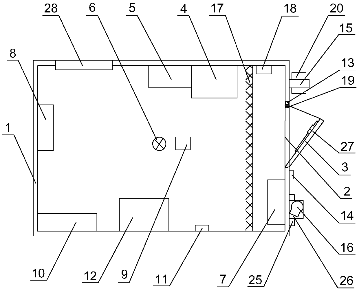
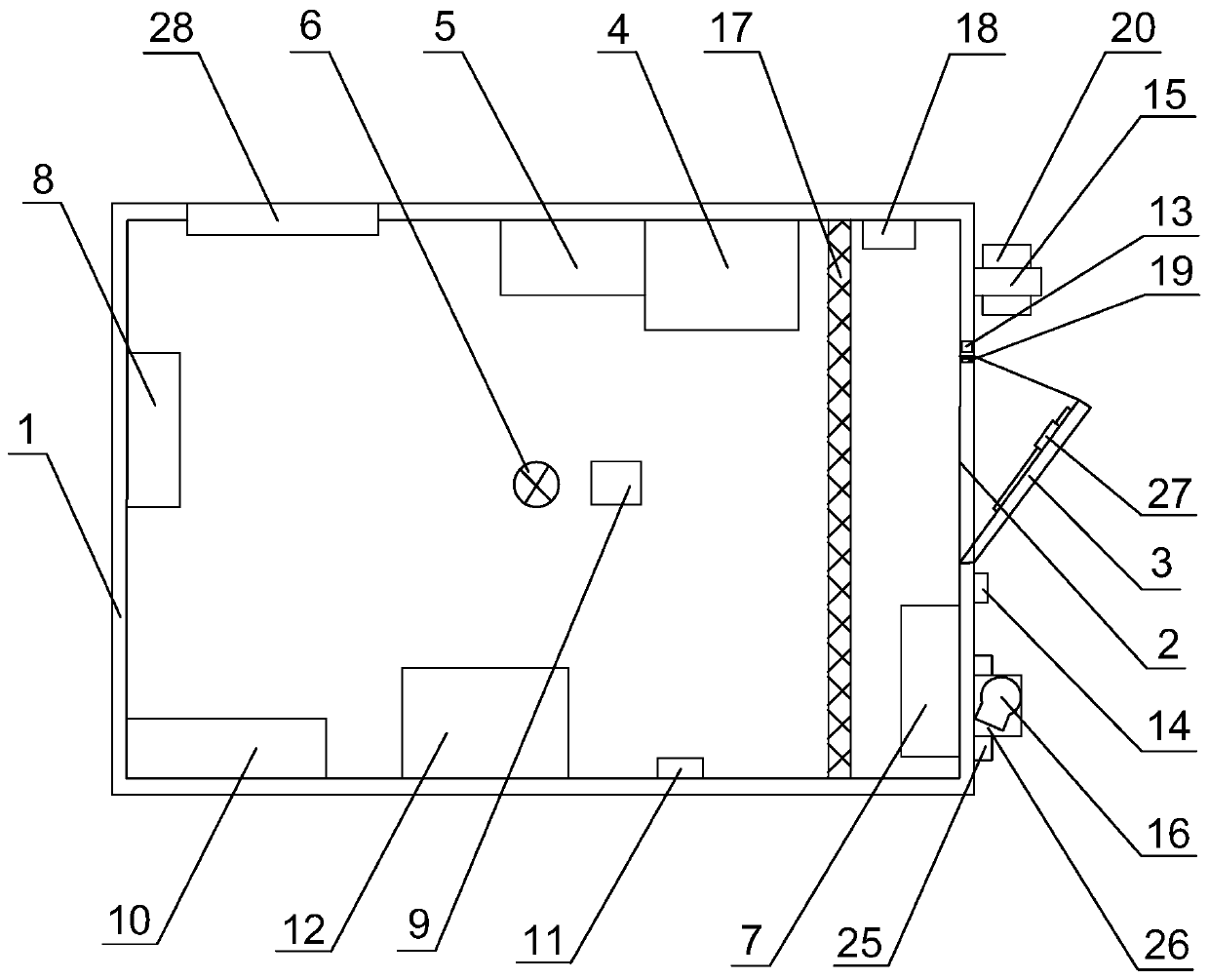
[0038] Reference figure 1 , Is a box intelligent monitoring and identification system disclosed in the present invention, including box body 1, box body 1 is rectangular parallelepiped shape and hollow inside, the bottom of box body 1 is fixed with a base, and cables are laid in the base. The inside of the box 1 is on the two inner side walls of the box 1 in turn, the power distribution cabinet 4, the remote terminal unit 5, the lighting lamp 6, the air conditioner 7, and the heating ventilator 8, and a smoke detector electrically connected to the remote terminal unit 5 is fixed. Detector 9, environmental temperature detector 10, sound and light alarm 11, temperature transmitter 12. During use, the power distribution cabinet 4 is used to supply power to the work site, and the illuminating lamp 6 illuminates the inside of the box 1 to facilitate the staff to observe the insid...


PUM


Abstract

The invention discloses an intelligent monitoring and identifying system of a box body, and relates to the technical field of an electronic control communication integrated box body. The problems thatthe working condition in the box body cannot be monitored in real time, and the anti-theft effect is poor are solved. The intelligent monitoring and identifying system comprises the box body, an entrance-exit is formed in one side of the box body, a safety door is also hinged thereto, and a power distribution cabinet, a remote terminal unit, an illumination lamp, an air conditioner, a smoke detector, an environment temperature detector, an audible and visual alarm and a temperature transmitter are fixed in the box body; and an isolation device is fixed in the box body, and a control button and a distance sensor are fixedly embedded on an inner wall of the entrance-exit, and an infrared sensor, a camera and a loudspeaker are arranged on an outer wall of the box body. The intelligent monitoring and identifying system disclosed by the invention can detect and monitor the real-time conditions at inside and outside the box body, identify a living body close to the box body and isolate anddrive away the non-workers, and can remotely control the box body, so that the monitoring work of the box body is easier and more convenient.

Description

Technical field [0001] The invention relates to the technical field of an integrated electronic control and communication box, in particular to a box intelligent monitoring and identification system. Background technique [0002] Nowadays, artificial intelligence has brought revolutionary changes to people’s production methods and lifestyles. In the field of oil and gas field development, it will gradually enter the era of intelligence. In the future, fully automatic drilling will be realized. Some key operations will be remotely controlled through on-site intelligence. The control platform combines ground intelligence and downhole intelligence into an organic whole. Through the Internet of Things, the on-site intelligent drilling and remote real-time intelligent control center form a large organic whole, realizing on-site + remote closed-loop control. The existing technology , The skid-mounted technology of power transmission, control, communication and other systems of drilling...

Claims


Application Information

Patent Timeline
Patent Type & Authority Applications(China)
IPC IPC(8): G05D23/20
CPCG05D23/20
Inventor 安录德胡强包莉达马志强
Owner SHANGHAI BAOLIN ELECTRIC GRP
Learn More