Air inlet passage structure and manufacturing method thereof

A manufacturing method and technology of air inlet, which is applied to the air inlet of turbine/propulsion device, combustion air/combustion-air treatment, engine components, etc., can solve problems such as energy consumption, flow separation method and mechanism complexity, and achieve or Delay boundary layer separation, achieve flow drag reduction effect, and maximize the effect

Inactive Publication Date: 2019-07-23
INST OF ENGINEERING THERMOPHYSICS - CHINESE ACAD OF SCI
View PDF6 Cites 2 Cited by
  • Summary
  • Abstract
  • Description
  • Claims
  • Application Information

AI Technical Summary

Problems solved by technology

[0005] Aiming at the existing technical problems, the present invention proposes an air inlet structure and its manufacturing method, which are used to solve the problems of complicated mechanisms and energy consumption in the existing control flow separation methods

Method used


Image

  • Air inlet passage structure and manufacturing method thereof
  • Air inlet passage structure and manufacturing method thereof
  • Air inlet passage structure and manufacturing method thereof

Examples


Embodiment Construction

[0031] In order to make the object, technical solution and advantages of the present invention clearer, the present invention will be described in further detail below in conjunction with specific embodiments and with reference to the accompanying drawings.

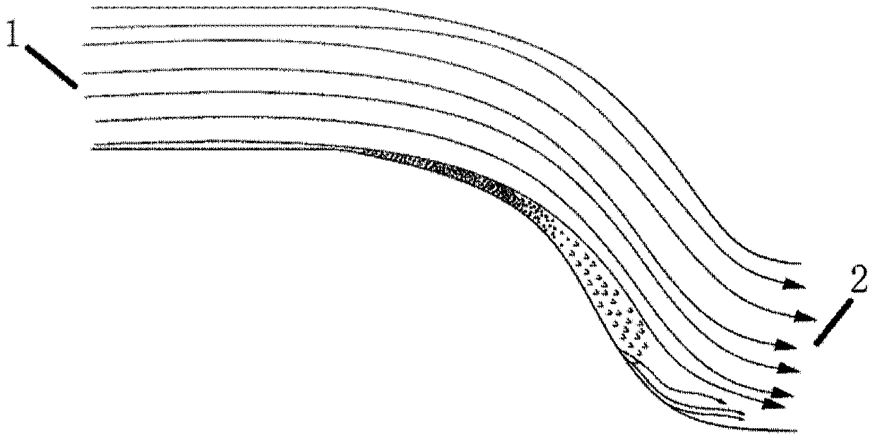
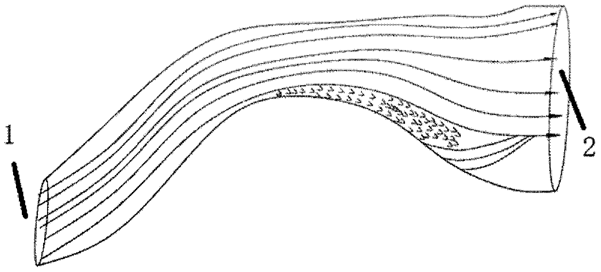
[0032] figure 1 and figure 2 They are the schematic diagrams of the existing typical S-curved inlet structure and the serpentine inlet structure respectively. It can be clearly seen from the figure that this inlet structure has an obvious boundary layer separation zone, and the separation zone will be at the exit. It evolves into a strong vortex distortion flow field, which affects the working performance of the engine body. From the perspective of the principle of boundary layer separation flow control, the purpose of controlling flow separation is to increase the ability of the boundary layer to resist the adverse pressure gradient. If the energy dissipation of the flow near the wall can be reduced by reducing the flo...


PUM


Abstract

The invention relates to an air inlet passage structure and a manufacturing method thereof. The air inlet passage structure is in an S shape or a snake shape, all areas or a part of area of the innerwall of the air inlet passage structure are / is of a porous structure, the thickness of pores in different areas of the inner wall of the air inlet passage structure and the number of the pores per unit area are the same or different, the shape of the pores in the porous structure is a circle, an ellipse or a polygon, and the porous structure has one layer or a plurality of layers, and the porous structure can realize suction and spraying of airflow of the inner wall of the air inlet structure. The air inlet structure transforms an existing typical air inlet passage inner wall or the local areainner wall into a porous medium structure, the sucking-spraying effect of the porous medium structure on fluid close to the wall is sufficiently used, the development of a near-wall flow boundary layer is destroyed, drag reduction of high-speed airflow in the air inlet is achieved, separation of the boundary layer flow is suppressed or delayed, and the problems that an existing air inlet flow control manner needs to increase additional energy and auxiliary mechanisms and the adaptivity is poor are solved.

Description

technical field [0001] The invention relates to the technical field of gas turbines, in particular to an air inlet structure and a manufacturing method thereof. Background technique [0002] The S-curve or serpentine inlet is one of the important parts of military engines. It can not only shorten the length of the inlet and improve the thrust-to-weight ratio, but also has good stealth. However, the S-curve or serpentine inlet has a large bend The angular structure will generate flow resistance to the high-speed inlet airflow. The S-shaped pipe expands along the flow direction and there is a large reverse pressure gradient. The high-speed airflow entering the intake pipe is difficult to attach to the inner wall of the extremely curved pipe, and flow separation is prone to occur. At the same time, due to the fact that there are two bends in different directions, when the main air flow passes through these two bends, due to the action of centrifugal force, the distribution of t...

Claims


Application Information

Patent Timeline
Patent Type & Authority Applications(China)
IPC IPC(8): F02C7/04
CPCF02C7/04
Inventor 李继超杜娟刘洋李帆张宏武
Owner INST OF ENGINEERING THERMOPHYSICS - CHINESE ACAD OF SCI
Why Eureka
Try Eureka