A cable-loaded crane device and installation method for installing suspension bridge stiffeners

A technology for cable-mounted cranes and suspension bridges, which is applied in the field of cable-mounted crane devices for installing suspension bridge stiff beams, and can solve problems such as reducing the stability of cable-mounted cranes, inability to realize on-load walking, and deflection and twisting of main cables. Achieve short lifting distance, improve efficiency, and solve the effect of deflection, twist, stress and deformation

Active Publication Date: 2020-09-11
HUNAN ZHONGNAN BRIDGE INSTALLATION ENG
View PDF5 Cites 0 Cited by
  • Summary
  • Abstract
  • Description
  • Claims
  • Application Information

AI Technical Summary

Problems solved by technology

Chinese invention patent CN106916354B discloses a cable-loaded crane that combines hoisting and walking. The acting point of the force is located above the main cable. During the process of walking with load, the main cable is prone to the risk of deflection and twisting when it is subjected to wind load, sunlight deflection, and lifting heavy objects. This reduces the risk of cable-loaded cranes. Walking stability, and this patent and the traditional cable-mounted crane walking wheel directly walk on the main cable, which is easy to cause damage to the main cable
However, due to the limitation of the traveling speed of the traditional cable-carried crane, it is impossible to realize the traveling with load. Generally, only one rigid beam segment can be installed every day, and the construction efficiency is very low.

Method used


Image

  • A cable-loaded crane device and installation method for installing suspension bridge stiffeners
  • A cable-loaded crane device and installation method for installing suspension bridge stiffeners
  • A cable-loaded crane device and installation method for installing suspension bridge stiffeners

Examples


Embodiment 1

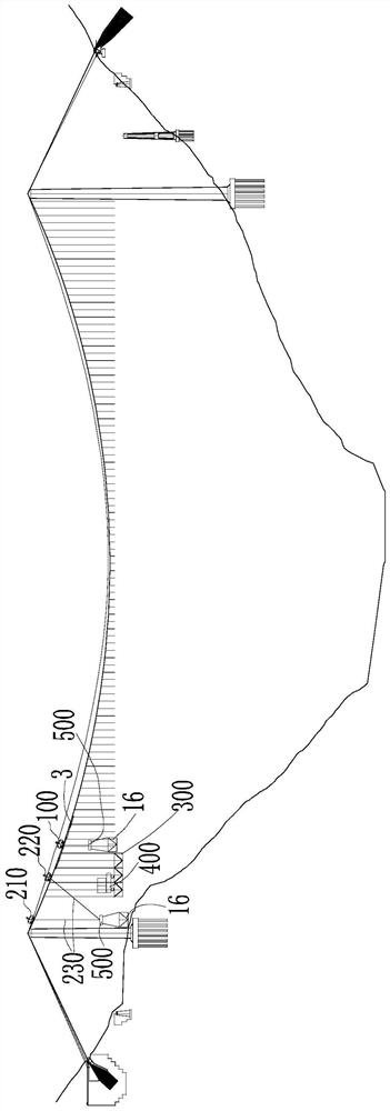
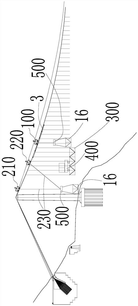
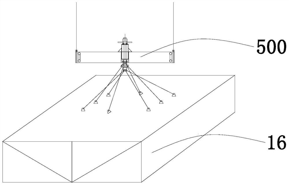
[0074] Such as figure 1 and figure 2 As shown, the cable-mounted crane device for installing the stiff beam of the suspension bridge in this embodiment includes a cable-mounted crane 200 and a mobile cable-mounted crane 100 installed on the main cable 10 of the suspension bridge and arranged at intervals, and The trolley 400 arranged on the stiff beam section 300, the stiff beam section 300 is assembled from a plurality of stiff beam sections 16, the trolley 400 is used to carry the stiff beam section 16 and can move along the longitudinal direction of the main cable 10 Move back and forth.

[0075] The cable-loaded crane 200 for lifting is arranged on one side of the stiff beam section 300 , and the cable-loaded crane 200 for lifting is used for hoisting the stiff beam section 16 onto the stiff beam section 300 . The hoisting cable-carrying crane 200 comprises a first cable-carrying crane 210 and a second cable-carrying crane 220 arranged at intervals on the main cable 10,...

Embodiment 2

[0109] Such as Figure 13 As shown, this embodiment is basically the same as Embodiment 1, and the only difference is that there are two sets of cable-mounted crane devices, and the two sets of cable-mounted crane devices are respectively arranged at both ends of the suspension bridge. This scheme installs stiff beams from both ends to the middle, which can further improve the installation efficiency of stiff beams.

[0110] Repeat step S2-step S7 to install the stiff beams of each segment in sequence, that is, install the stiff beams from the two towers to the mid-span.

Embodiment 3

[0112] Such as Figure 14 As shown, this embodiment is basically the same as Embodiment 1, and the only difference is that: both sides of the lifting cable crane 200 are provided with a stiff beam section 300 and a carrying cable crane 100 . This solution installs stiff beams from the middle to both ends, which can not only further improve the installation efficiency, but also reduce equipment investment.

[0113] Repeat step S2-step S6 of embodiment 1 to install the stiff beams of each segment in sequence, that is, install the stiff beams from the mid-span to the two cable towers; install the two mid-span stiff beams according to the method of step S7.


PUM


Abstract

The invention discloses a cable carrying crane device for installation of a stiff beam of a suspension bridge. The cable carrying crane device comprises a cable carrying crane for hoisting and a cablecarrying crane for carrying, wherein the cable carrying crane for hoisting and the cable carrying crane for carrying are installed on a main cable of the suspension bridge and arranged in a separatedmode. The cable carrying crane for hoisting is arranged on one side of a stiff beam section, and the stiff beam section is formed by multiple stiff beam segments in an assembly mode, and the cable carrying crane for hoisting is used for hoisting the stiff beam segments to the stiff beam section. The cable carrying crane for carrying can carry the load to move back and forth in the longitudinal direction of the main cable and is used for carrying the stiff beam segments on the stiff beam section to the other side of the stiff beam section so that the stiff beam segments and the stiff beam section can be assembled. The cable carrying crane for carrying comprises a special travelling rail mechanism which is fixedly connected with the main cable, and the cable carrying crane for carrying cantravel on the travelling rail mechanism in a load-carrying state. According to the cable carrying crane device, the double cable carrying cranes are adopted to cooperate so as to achieve installationof the stiff beam, the construction efficiency of the stiff beam can be improved, and the cable carrying crane device has the advantages of being safe and reliable, causing no damage to the main cableand the like.

Description

technical field [0001] The invention relates to the technical field of bridge construction, in particular to a cable-mounted crane device and an installation method for installing stiff beams of suspension bridges. Background technique [0002] Suspension bridge, also known as suspension bridge, refers to a bridge with two main cables spaced along the width direction of the bridge that are suspended by cable towers and anchored on both sides (or at both ends of the bridge) as the main load-bearing components of the upper part. With the rapid development of long-span suspension bridges in our country, cable-loaded cranes have been used as special lifting equipment for vertically lifting and installing the stiff beams of suspension bridges. Stiff girders of suspension bridges are usually processed into segments in the factory or on site, and the stiff girder segments are transported to the right below the lifting position by ship, and the stiff girder is hoisted vertically or ...

Claims


Application Information

Patent Timeline
Patent Type & Authority Patents(China)
IPC IPC(8): B66C21/00E01D21/00
CPCB66C21/00E01D21/00
Inventor 陈维超杨世湘杨鑫余海张艳春
Owner HUNAN ZHONGNAN BRIDGE INSTALLATION ENG
Why Eureka
Try Eureka