Lathe fastener
A lathe and accommodating slot technology, applied in the directions of large fixed members, metal processing machinery parts, metal processing equipment, etc., can solve the problems of troublesome processing, power consumption, affecting the demand for rapid exchange of worktables, etc., and achieve the effect of environmental protection maintenance
Inactive Publication Date: 2010-12-01
FACTORY AUTOMATION TECH CO LTD
View PDF0 Cites 0 Cited by
- Summary
- Abstract
- Description
- Claims
- Application Information
AI Technical Summary
Problems solved by technology
1. The fastening device protrudes: when the worktable is to be released, the clamping claws of the fastening device protrude from the joint surface of the fastening device and the workbench, so when the workbench is replaced, the required upward stroke is relatively large, which affects the rapid exchange Workbench requirements, and there is a possibility of interference when the workbench is exchanged
2. The use of oil pressure devices is not environmentally friendly: the oil in the oil pressure device will cause environmental pollution, troublesome disposal, and consume electricity. The oil tank takes up a lot of space and requires regular maintenance, which is not economical.
Method used
View moreImage
Smart ImageViewing Examples
Examples
Embodiment Construction
Login to View More PUM
 Abstract
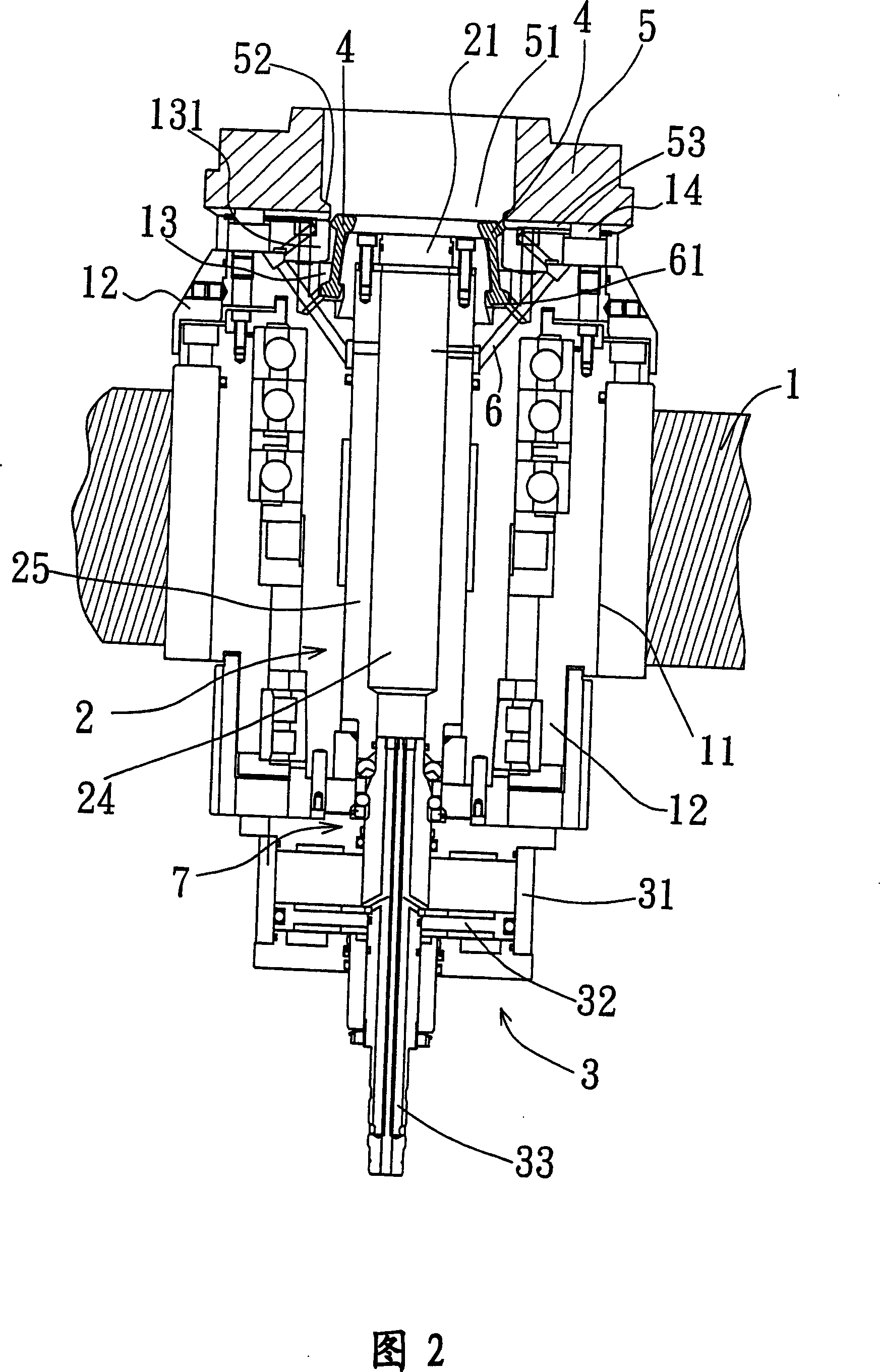
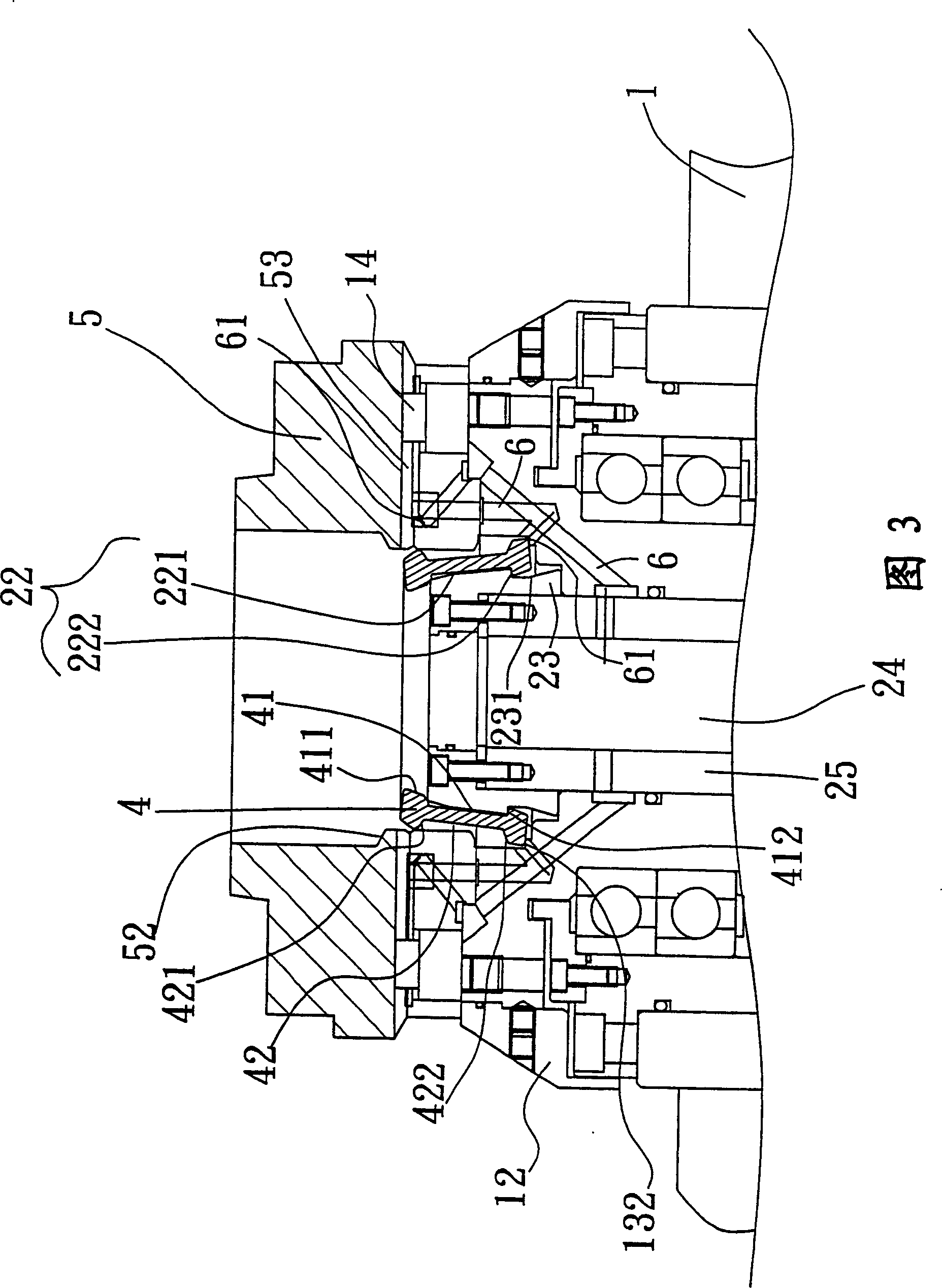
The invention is concerned with a kind of fixing and tightening equipment to lathe, relating to a platform, a movable axis, a drive source, holding blocks in complex number and a workbench. The platform has a fixed axis seat and one end of axis seat contains a holding groove with protruding part and moveable axis. The head of moveable axis is protruding and sets in the holding groove. The drive source affords the drive to move up and down connecting with the moveable axis. The holding blocks are arranged as a ring on the space between the head of axis and the inner wall of holding groove. There are inner groove and outer groove on the inner and outer sides of each holding block, and the bottom of platform has hemline sticking out to inner with alcove, and the alcove matches with the holding groove. When the workbench is on the axis seat, the moveable axis moves upside and the head of axis pushes the holding block to move upside till the outer groove matches with the protruding part and hemline. It fixes the workbench on the platform tightly, and on the contrary, the moveable axis moves down will release the workbench.
Description
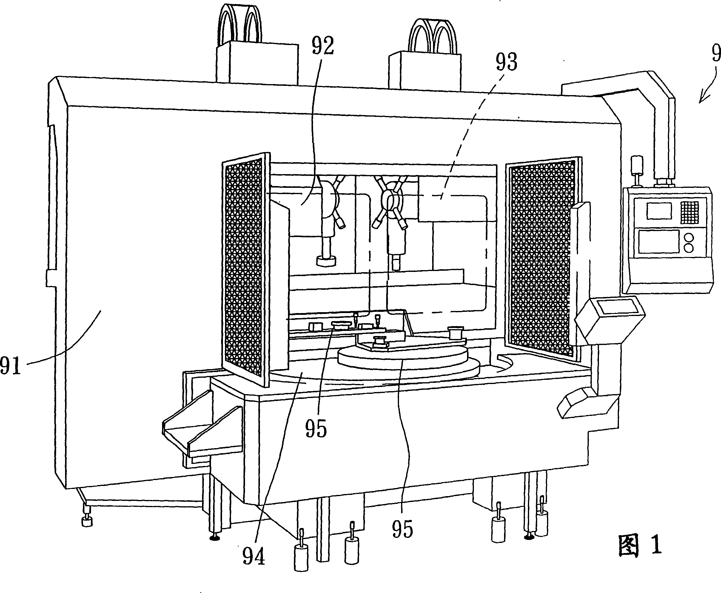
Fasteners for lathes technical field The invention relates to a fastening device for a lathe, especially a fastening device that releases the workbench in a retracted manner, which avoids interference when the workbench is exchanged, and the lifting stroke required for the exchange is short, improving the exchange speed and safety Suitable for all kinds of lathes. Background technique Lathe is an important tool for workpiece processing. According to the angle of cutting tool placement, it is mainly divided into horizontal lathe and vertical lathe. Please refer to Figure 1. It is a type of vertical lathe currently available. The vertical lathe 9 Including a machine table 91, a cutting tool 92, two door panels 93, a turntable 94 and two worktables 95, the cutting tool 92 is arranged in the processing space in the machine table 91, and the two door panels 93 can be opened and closed on the machine table 91. When a workbench 95 with a fixed workpiece (not shown) enters the pr...
Claims
Login to View More Application Information
Patent Timeline
 Patent Type & Authority Patents(China)
IPC IPC(8): B23Q1/26B23Q1/66
Inventor 卢永祥林忠龙
Owner FACTORY AUTOMATION TECH CO LTD
Features
- R&D
- Intellectual Property
- Life Sciences
- Materials
- Tech Scout
- Unparalleled Data Quality
- Higher Quality Content
- 60% Fewer Hallucinations
Learn More Browse by: Latest US Patents, China's latest patents, Technical Efficacy Thesaurus, Application Domain, Technology Topic, Popular Technical Reports.
© 2025 PatSnap. All rights reserved.Legal|Privacy policy|Modern Slavery Act Transparency Statement|Sitemap|About US| Contact US: help@patsnap.com


