
Automated power ramp

A power and ramp technology, applied in drill pipes, casings, drill pipes, etc., can solve the problems of high labor intensity and low efficiency, and achieve the effect of short lifting distance, high efficiency, and reduced manual operation intensity.

Active Publication Date: 2018-11-30
QINGDAO TAIZHONG ENERGY TECH
View PDF9 Cites 0 Cited by
  • Summary
  • Abstract
  • Description
  • Claims
  • Application Information

AI Technical Summary

Problems solved by technology

[0003] The purpose of the present invention is to solve the problems of high labor intensity and low efficiency that require personnel to operate the air winch to pull the drill pipe from the catwalk in the traditional ramp, and provide an automatic power ramp

Method used


Image

  • Automated power ramp
  • Automated power ramp
  • Automated power ramp

Examples


Embodiment Construction

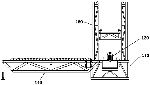
[0014] The automatic power ramp of the present invention will be described in detail below in conjunction with the accompanying drawings and embodiments.

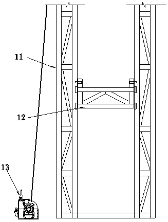
[0015] like figure 1 As shown, the automatic power ramp is composed of a base mechanism 110, a power catwalk mechanism 120, a lifting guide rail 130 and a drill rod rack mechanism 140; The moving device slides on the guide rail; the air winch is connected with the power catwalk mechanism 120 to provide power for the power catwalk mechanism; the power catwalk mechanism 120 is arranged on the sliding device, and can slide through the sliding device on the base. , and the bracket on the lifting guide rail 130 is fixed with a fixed pin, and can be rotated along the pin shaft during the ascent process; the drill rod rack mechanism 140 is connected with the pin shaft of the base, and is supported on the ground through the lifting hydraulic cylinder; the lifting guide rail 13-and the base The flange plate is fixed by a fixed pin,...


PUM


Abstract

The invention belongs to the technical field of petroleum drilling and relates to an automated power ramp. The automated power ramp comprises a base mechanism, a power catwalk mechanism, lifting guide rails and a drill rod rack mechanism. The base mechanism comprises a base, a pneumatic winch and a sliding device, the base is provided with guide rails, and the sliding device can slide on the guide rails; the pneumatic winch is connected with the power catwalk mechanism; the power catwalk mechanism is arranged on the sliding device and can slide through the sliding device on the base, and is fixed onto a bracket of the lifting guide rails through fixing pins during lifting; the drill rod rack mechanism is hinged to the base through hinge pins and is supported on the ground through a lifting hydraulic cylinder; the lifting rails and a base flange are fixed through fixing pins, and the upper ends of the lifting guide rails and a drill floor structure are fixed through hinge pins. According to the automated power ramp, the ramp is designed to be driven by power and is lifted to the height of a drill floor surface in a perpendicular mode, so that the lifting distance is short and the efficiency is high, a drill rod rack is driven by hydraulic cylinder power and can automatically convey drill rods to a catwalk, so that the intensity of manual operation is reduced.

Description

technical field [0001] The invention belongs to the technical field of petroleum drilling and relates to an automatic power ramp. . Background technique [0002] In the oil drilling industry, a single drill pipe is dragged from the catwalk along the ramp to the fixed mouse hole by manually operating the gas winch, and then the top drive lifts the drill pipe to start the operation of connecting the column. Low efficiency, relying on manual operation, high labor intensity and high risk. Some products use power ramps, but the drill pipes need to be manually transported from the drill pipe rack to the catwalk, without lifting guide rails, relying on traditional ramps for guide rail lifting, the speed is slow and the efficiency is low. Contents of the invention [0003] The purpose of the present invention is to solve the problems of high labor intensity and low efficiency that the traditional ramp requires personnel to operate the air winch to pull the drill pipe from the ca...

Claims


Application Information

Patent Timeline
Patent Type & Authority Patents(China)
IPC IPC(8): E21B19/14
Inventor 刘世滨
Owner QINGDAO TAIZHONG ENERGY TECH
Learn More