
A fluid shunt drag reducer

A technology of fluid diversion and drag reducer, which is applied in the direction of fluid dynamics/hydrostatics characteristics, hull, hull design, etc. It can solve problems such as large air resistance, damage to the normal use of equipment, and increase in hull speed, so as to reduce the front Squeeze problems, improve speed and stability, and reduce fluid resistance

Active Publication Date: 2021-10-08
SHENZHEN SHANNIAN SCI & TECH
View PDF21 Cites 0 Cited by
  • Summary
  • Abstract
  • Description
  • Claims
  • Application Information

AI Technical Summary

Problems solved by technology

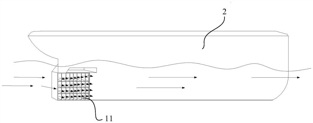
[0002] At present, when various equipment, such as the hull is running, its front end will bear the resistance from the fluid, that is, water. As the speed of the hull increases, the volume of the water flow facing the bow will increase exponentially. The effect of timely diversion will form a superimposed effect with the surrounding water environment, which will have a greater impact on the speed and stability of the hull; especially when the speed of the ship reaches a certain speed, it will form a marginal effect, so that even if the hull Doubling the power does not significantly increase the speed of the hull
At the same time, in other equipment, such as rocket launching high-speed aircraft, etc., due to the defect of air shunt effect when traveling at high speed, not only the air resistance is huge, but also the high temperature will damage the normal use of the equipment.

Method used


Image

  • A fluid shunt drag reducer
  • A fluid shunt drag reducer
  • A fluid shunt drag reducer

Examples


Embodiment Construction

[0028] The following will clearly and completely describe the technical solutions in the embodiments of the present invention with reference to the accompanying drawings in the embodiments of the present invention. Obviously, the described embodiments are only part of the embodiments of the present invention, not all of them. Based on the embodiments of the present invention, all other embodiments obtained by persons of ordinary skill in the art without creative efforts fall within the protection scope of the present invention.

[0029] It should be noted that if there is a directional indication (such as up, down, left, right, front, back...) in the embodiment of the present invention, the directional indication is only used to explain the position in a certain posture (as shown in the accompanying drawing). If the specific posture changes, the directional indication will also change accordingly.

[0030] In addition, if there are descriptions involving "first", "second" and ...


PUM


Abstract

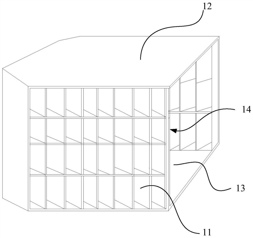
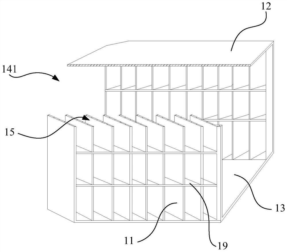
The invention discloses a fluid flow splitting drag reducer. The fluid flow splitting drag reducer comprises a plurality of flow splitting pieces and a connecting piece connecting the plurality of flow splitting pieces into a whole; the plurality of the flow splitting pieces and the connecting piece are enclosed by A column-shaped distribution cavity for fluid to enter is formed, and the distribution cavity has a central axis; when the fluid enters the distribution cavity, the flow direction is from the front to the rear, and the front opening of the distribution cavity forms a main flow hole; The diverting pieces are arranged at intervals in the direction along the central axis, and in the front-to-rear direction along the central axis, the included angle between the diverting piece and the central axis is an acute angle ; The interval between two adjacent said diverting pieces forms a diverting hole communicating with said distribution cavity. The technical scheme of the present invention can reduce the fluid resistance of the equipment when it travels in a fluid environment, and improve the energy consumption efficiency and stability of the equipment when it travels.

Description

technical field [0001] The invention relates to the technical field of diverters, in particular to a fluid diverter drag reducer. Background technique [0002] At present, when various equipment, such as the hull is running, its front end will bear the resistance from the fluid, that is, water. As the speed of the hull increases, the volume of the water flow facing the bow will increase exponentially. The effect of timely diversion will form a superimposed effect with the surrounding water environment, which will have a greater impact on the speed and stability of the hull; especially when the speed of the ship reaches a certain speed, it will form a marginal effect, so that even if the hull Doubling the power also cannot significantly increase the speed of the hull. At the same time, in other equipment, such as rocket launching high-speed aircraft, due to the defect of air shunt effect when traveling at high speed, not only the air resistance is huge, but also high tempera...

Claims


Application Information

Patent Timeline
Patent Type & Authority Patents(China)
IPC IPC(8): B63B1/40
CPCB63B1/40Y02T70/10
Inventor 彭学龙
Owner SHENZHEN SHANNIAN SCI & TECH
Learn More