
Rotatable cup holder

A cup holder and rotating bearing technology, applied in the field of daily life, can solve the problems of poor aesthetics, poor artistry, inconvenient to take the cup, fixed cup holder, etc., so as to avoid the broken white wine glass and increase the use Extensive, fast installation effect

Pending Publication Date: 2019-07-23
JIANGMEN CITY PENGJIANG DISTRICT JIUSHANG TRADING CO LTD
View PDF0 Cites 0 Cited by
  • Summary
  • Abstract
  • Description
  • Claims
  • Application Information

AI Technical Summary

Problems solved by technology

The traditional cup holder is generally a plate structure, that is, a plate, made of wood, plastic or metal and other materials, the structure is simple, but the aesthetics and artistry are not good enough; and the traditional cup holders are fixed. It is not very convenient when people need to take the cup; The use of the inconvenience

Method used


Image

  • Rotatable cup holder
  • Rotatable cup holder
  • Rotatable cup holder

Examples


Embodiment 1

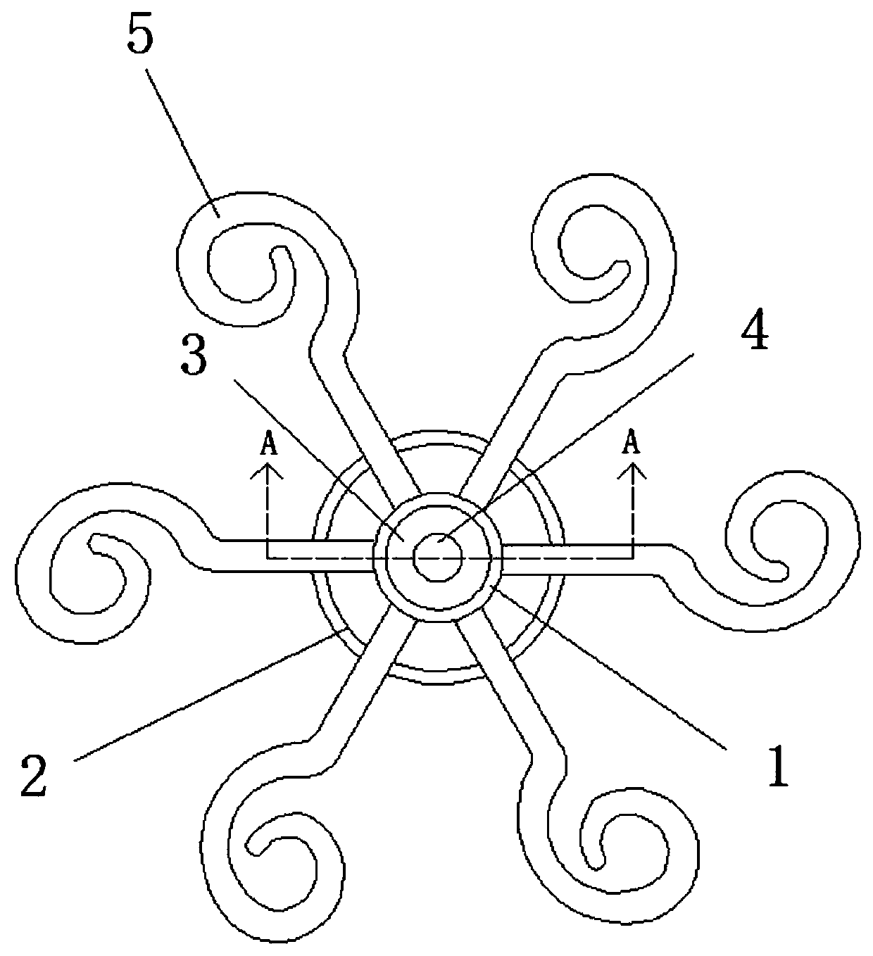
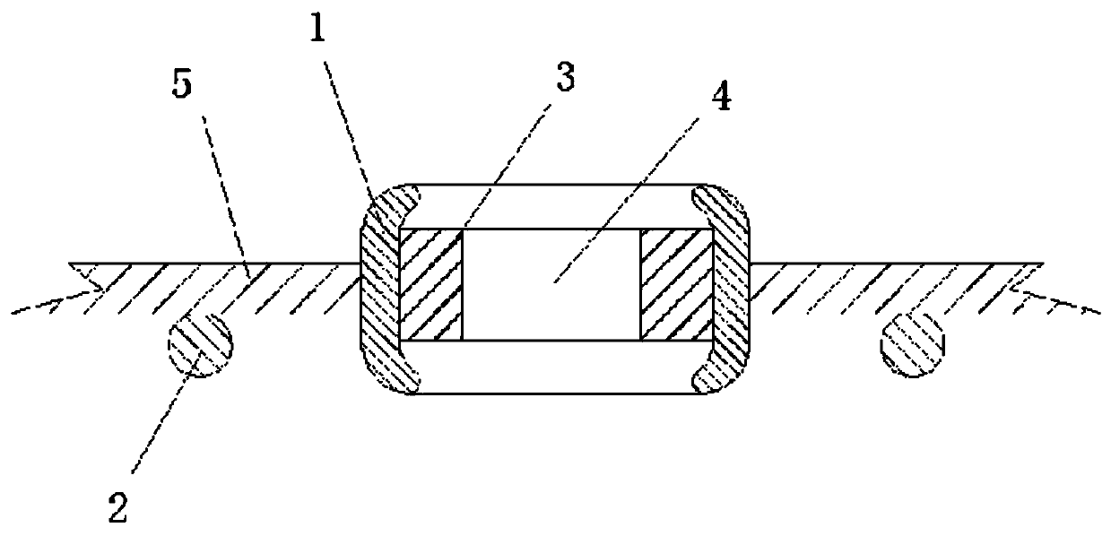
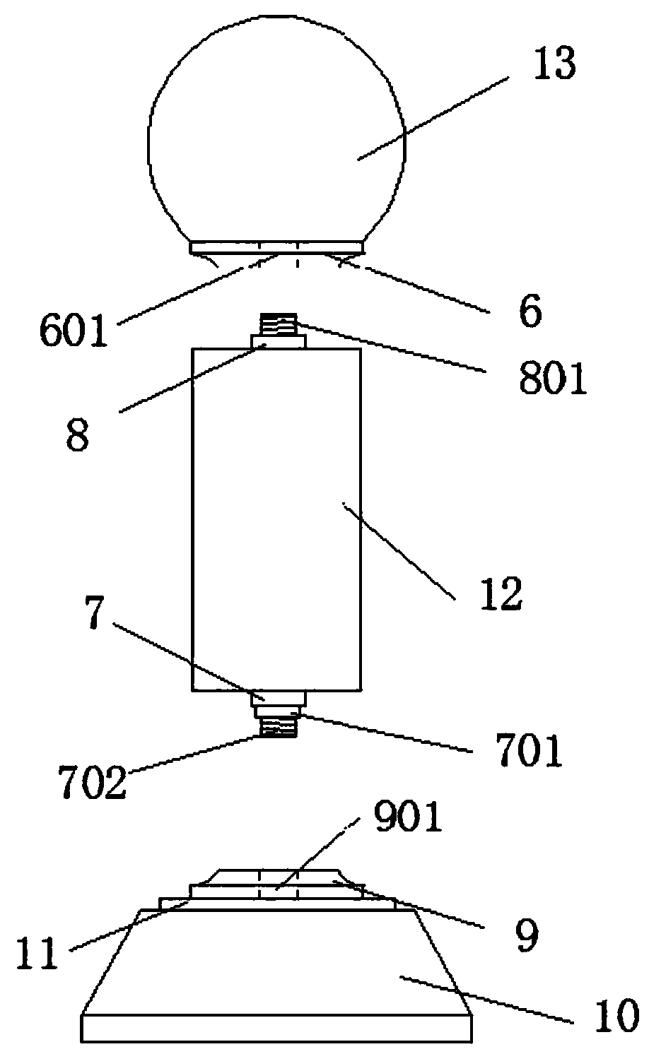
[0019] Embodiment 1, as figure 1 , figure 2 and image 3 As shown, a rotatable cup holder includes a placement frame body and a support column, and the placement frame body is connected to the support column. The placement frame body includes a fixed sleeve 1, a rotating bearing 3, and a curved rod 5; the fixed sleeve 1 is hollow Tubular, the fixed sleeve 1 is connected with several curved rods 5, the curved rods 5 are strips, one end of the curved rod 5 is fixedly connected with the outer surface of the fixed sleeve 1, and the other end is spirally curled; the fixed sleeve 1 is socketed On the outside of the swivel bearing 3 and the inner side wall of the fixed sleeve 1 is connected to the outer side wall of the swivel bearing 3 without clearance, the center position of the swivel bearing 3 is provided with a bearing through hole 4 and is connected to the supporting column through the bearing through hole 4; the supporting column includes a base 10 , column 12, ball seat 1...

Embodiment 2

[0020] Embodiment 2, as figure 1 , figure 2 and Figure 4 As shown, a rotatable cup holder includes a placement frame body and a support column, and the placement frame body is connected with the support column. The placement frame body includes a fixed sleeve 1, a rotating bearing 3, a curved rod 5, and a reinforcement sleeve 2; The sleeve 1 is in the shape of a hollow tube, and the fixed sleeve 1 is connected with several curved rods 5. The curved rods 5 are strips. One end of the curved rod 5 is welded to the outer surface of the fixed sleeve 1, and the other end is spirally curled; The lower end of the rod 5 is welded with a reinforcing sleeve 2, which improves the load-bearing capacity and fixability of the curved rod 5; the edges of the upper and lower ends of the fixing sleeve 1 are inwardly curved, and the bending angle is not greater than 90 degrees; this design can make the fixed The connection between the sleeve 1 and the rotary bearing 3 is more stable, which im...


PUM


Abstract

The invention discloses a rotatable cup holder. The rotatable cup holder comprises a placement holder body and a supporting column, and the placement holder body is connected with the supporting column and comprises a fixing sleeve, a rotation bearing and multiple curved rods; the fixing sleeve is connected with the curved rods, the rotation bearing is embedded in the fixing sleeve and connected with the fixing sleeve, a bearing through hole is formed in the center of the rotation bearing, and the rotation bearing is connected with the supporting column through the bearing through hole; the supporting column comprises a base, a column and a ball seat; a first threaded base is fixedly connected with the upper end of the base, and a first threaded hole is formed in the first threaded base; asecond threaded base is fixedly connected with the bottom of the ball seat, and a second threaded hole is formed in the second threaded base; a first connection base is fixedly connected with one endof the column and is connected with the first threaded hole or the second threaded hole after penetrating through the bearing through hole; a second connection base is fixedly connected with the other end of the column and connected with the first threaded hole or the second threaded hole.

Description

technical field [0001] The invention relates to the field of daily life, in particular to a rotatable cup holder. Background technique [0002] The cup holder is a very widely used storage rack, which can be used to place teacups, wine glasses and other utensils to keep the cups and tea clean. The traditional cup holder is generally a plate structure, that is, a plate, made of wood, plastic or metal and other materials, the structure is simple, but the aesthetics and artistry are not good enough; and the traditional cup holders are fixed. It is not very convenient when people need to take the cup; The use has brought inconvenience. Contents of the invention [0003] The purpose of the present invention is to solve the above problems and provide a rotatable wine rack with simple structure and convenient use. [0004] In order to achieve the above object, technical scheme of the present invention is: [0005] A rotatable cup holder, comprising a placement frame body and ...

Claims


Application Information

Patent Timeline
Patent Type & Authority Applications(China)
IPC IPC(8): A47G23/02
CPCA47G23/02
Inventor 崔勇
Owner JIANGMEN CITY PENGJIANG DISTRICT JIUSHANG TRADING CO LTD
Learn More