Clamping device for machining PCB and equipped with flexible clamping body structure

A flexible clamping and PCB board technology, applied in the direction of circuit board tool positioning, electrical components, printed circuit manufacturing, etc., can solve the problems of PCB edge damage, PCB board falling off, poor clamping effect, etc., to ensure production quality , Guarantee stability, improve the effect of quality inspection efficiency

Active Publication Date: 2019-07-19
苏州有容电子有限公司
View PDF9 Cites 2 Cited by
  • Summary
  • Abstract
  • Description
  • Claims
  • Application Information

AI Technical Summary

Problems solved by technology

[0006] In order to solve the above technical problems, the present invention provides a clamping device for PCB board processing equipped with a flexible clamping body structure to solve the problem that although the clamps are used in different fields, their functions are similar, and they all play an auxiliary clamping role. On the whole, after searching the above invention and combining the existing technology, we found that the existing similar clamping device is in use, and the clamping effect on the edge of the PCB board is poor, and the PCB board is easy to fall off from the inside of the device, resulting in the clamping of the PCB board. The stability, and the flexible protection effect on the edge of the PCB board is poor, and it is easy to cause damage to the edge of the PCB board when clamping and fixing, which affects the processing quality of the PCB board

Method used


Image

  • Clamping device for machining PCB and equipped with flexible clamping body structure
  • Clamping device for machining PCB and equipped with flexible clamping body structure
  • Clamping device for machining PCB and equipped with flexible clamping body structure

Examples


Embodiment

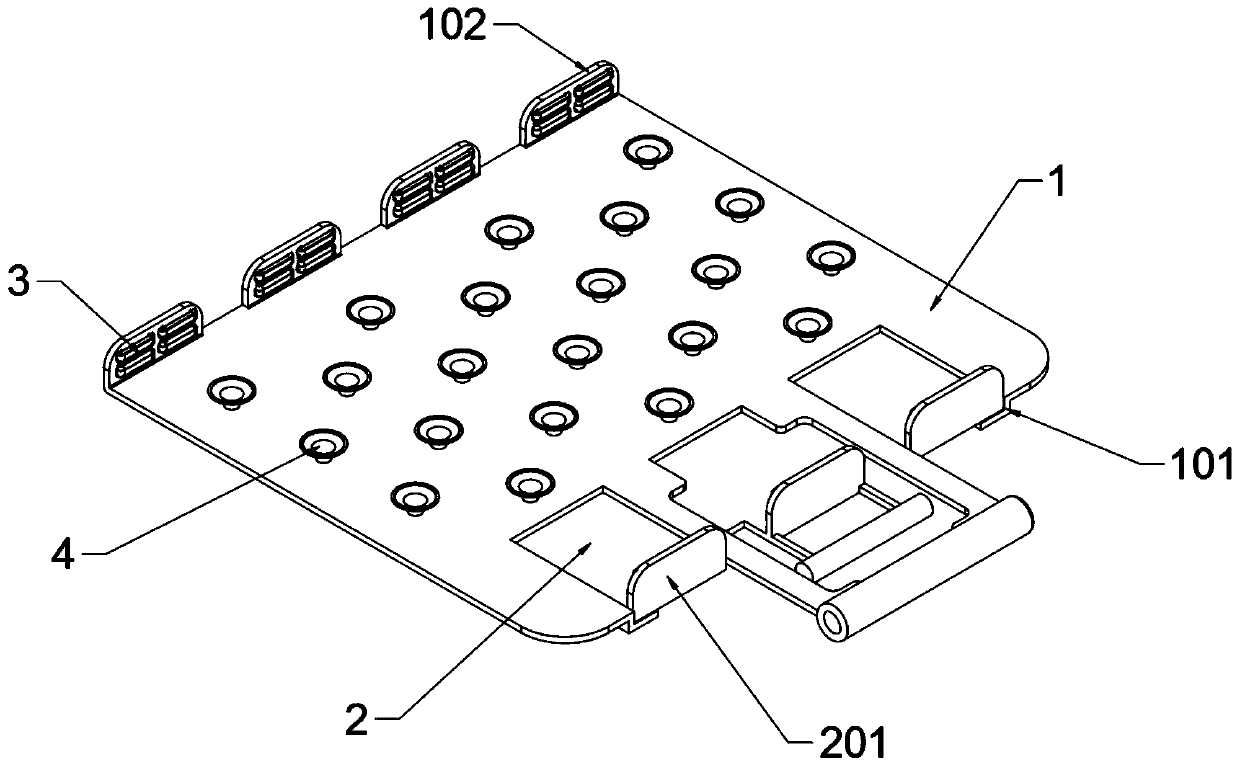
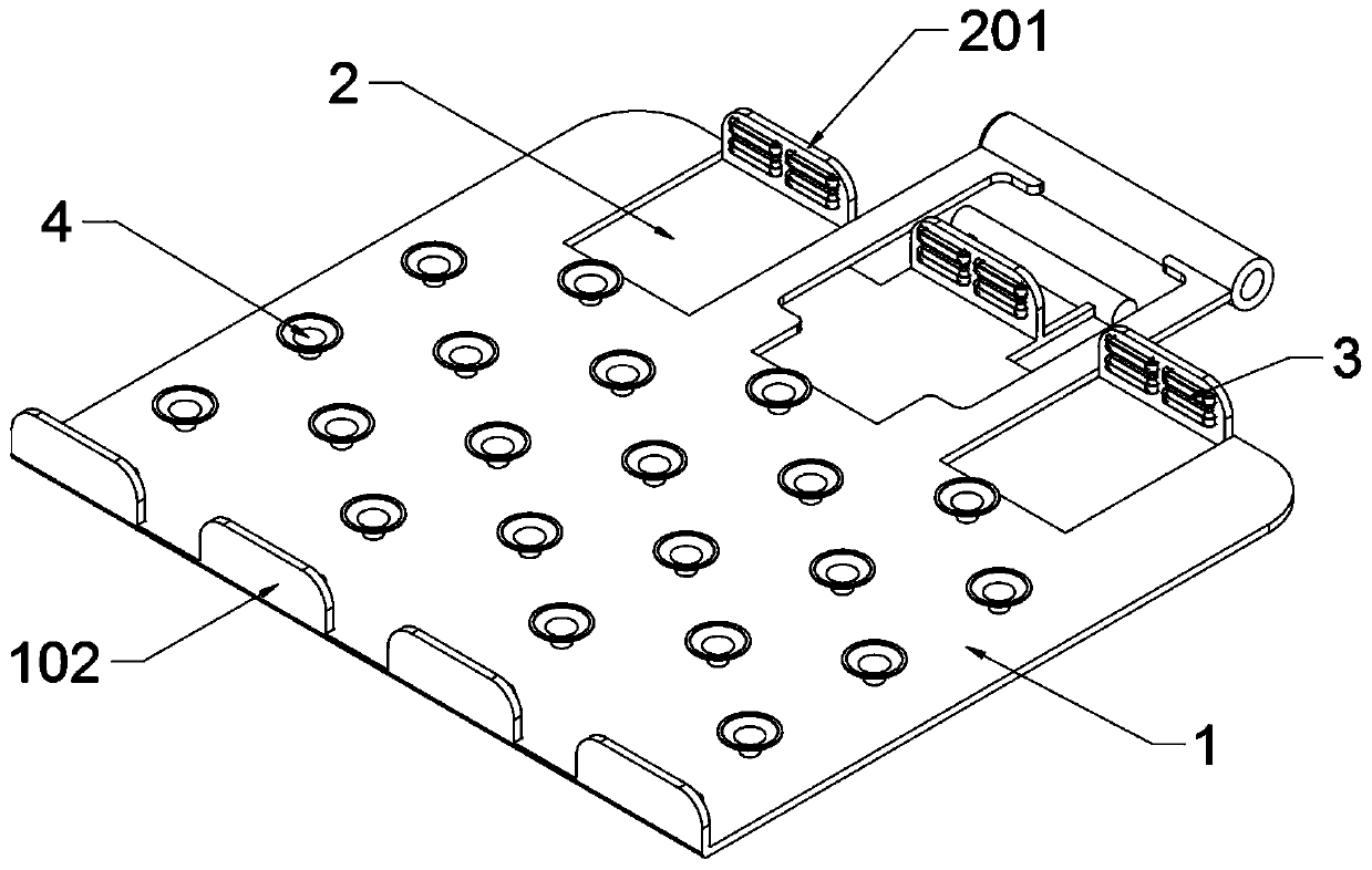
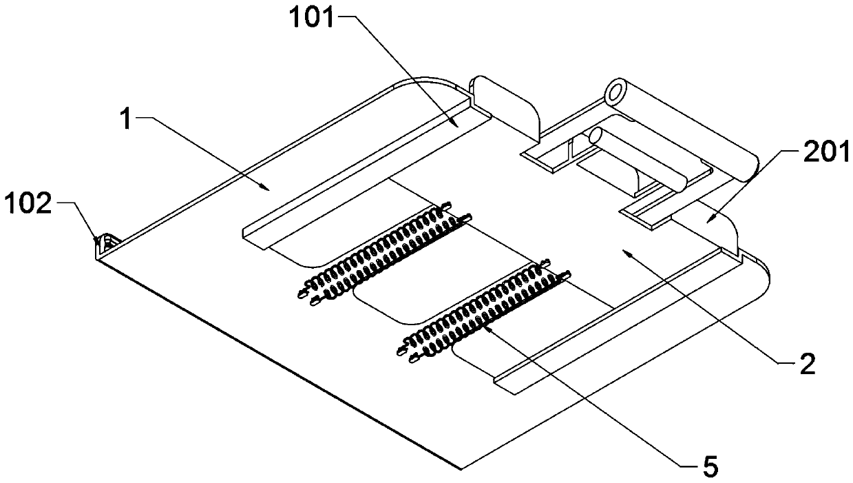
[0035] As attached figure 1 Attached Picture 10 Shown:

[0036] The present invention provides a clamping device for PCB board processing with a flexible clamping body structure. The clamping device includes a clamping plate 1, a sliding groove 101, a main clamping block 102, a movable clamping plate 2, an auxiliary clamping block 201, a latex block 3, and a flexible Suction cup 4, tension spring 5, support frame 6, support seat 7, transmission shaft 8, transmission belt 9, non-slip convex strip 901, transmission motor 10 and control electric box 11; the clamping plate 1 is a rectangular plate structure and clamps The right end of the holding plate 1 is a handle-shaped structure; the movable splint 2 is located at the bottom of the holding plate 1, and the right end of the movable splint 2 is a handle-shaped structure, and the holding plate 1 and the movable splint 2 are made of transparent plastic; the latex The block 3 has fourteen places, and the latex block 3 is respectivel...


PUM


Abstract

The invention provides a clamping device for machining a PCB and equipped with a flexible clamping body structure. The clamping device comprises a transmission motor and a control electric box; the clamping plate is of a rectangular plate-shaped structure, and the right end of the clamping plate is of a handle-shaped structure; a movable clamping plate is located at the bottom of the clamping plate, the right end of the movable clamping plate is of a handle-shaped structure, and both the clamping plate and the movable clamping plate are made of transparent plastic; latex blocks are arranged atfourteen positions, and the latex blocks are arranged on the outer side end surfaces of a main clamping block and an auxiliary clamping block, so that the main clamping block and the auxiliary clamping block are attached to the left end and the right end of the PCB respectively, the PCB is fixed inside the clamping plate, the PCB is conveniently detected by workers, and the production quality ofthe PCB is guaranteed; and the use of a tension spring is matched, so that the movable clamping plate can be driven to slide in a sliding groove at the bottom of the clamping plate, so that the main clamping block at the left end of the clamping plate 1 and the auxiliary clamping block at the right end of the movable clamping plate can be more tightly attached to the left end and the right end ofthe PCB under the influence of tension of tension spring, thereby ensuring the clamping stability of the PCB.

Description

Technical field [0001] The invention belongs to the technical field of PCB board processing, and more specifically, relates to a clamping device for PCB board processing equipped with a flexible clamping body structure. Background technique [0002] With the development of technology, the demand for PCB boards is also increasing year by year. In order to meet higher requirements, PCB boards often adopt a multi-layer composite form, and the corresponding manufacturing processes are more complicated. In order to effectively monitor the production quality during the production process, a combination of automatic detection and manual detection is usually used, which requires a special PCB board clamping device to assist in fixing. [0003] For example, the application number application number: 201710942533.5 is a steel pipe processing and clamping device. The present invention discloses a steel pipe processing and clamping device, including a seat plate. The top of the seat plate is ...

Claims


Application Information

Patent Timeline
Patent Type & Authority Applications(China)
IPC IPC(8): H05K3/00
CPCH05K3/0008H05K2203/1509H05K2203/163
Inventor 王薪皓
Owner 苏州有容电子有限公司
Why Eureka
Try Eureka