
Airborne photoelectric system target motion vector estimation method based on aerial photography measurement

A photoelectric system, technology of motion vectors, applied in the direction of radio wave measurement systems, devices that use to measure the time required to move a certain distance, calculations, etc.

Pending Publication Date: 2019-07-19
西安应用光学研究所
View PDF5 Cites 8 Cited by
  • Summary
  • Abstract
  • Description
  • Claims
  • Application Information

AI Technical Summary

Problems solved by technology

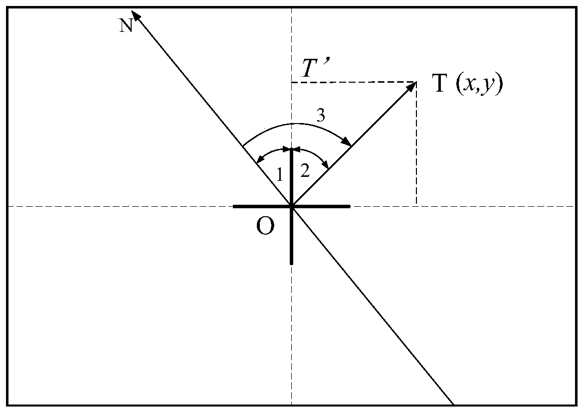
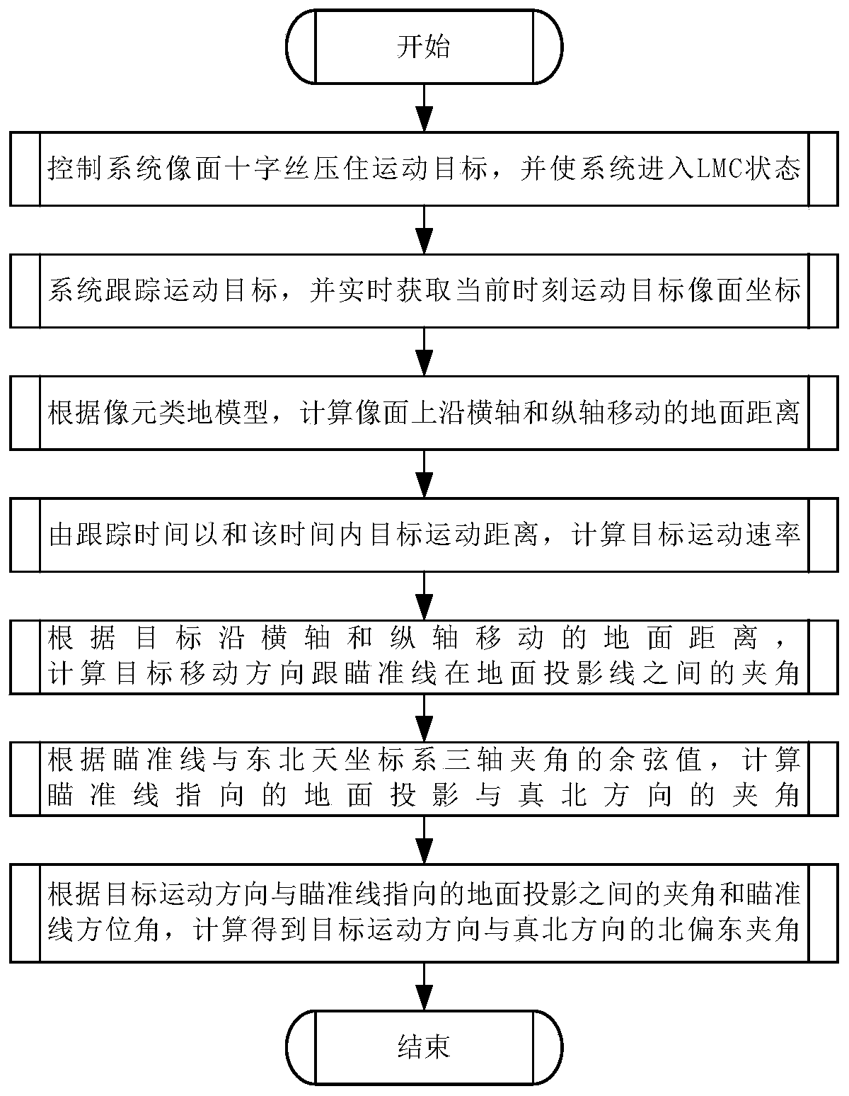
[0005] In order to solve the problem of estimating the motion vector of the ground target in the existing airborne optoelectronic system and improve the estimation accuracy of the motion vector of the long-distance target, the present invention proposes a method for estimating the target motion vector of the airborne optoelectronic system based on aerial photogrammetry with the help of photogrammetry theory. A ground-like model of long-distance photogrammetry pixels is established, using the motion vector of the ground moving target in the image space coordinate system, through the coordinate system conversion between the image space coordinate system and the ground photogrammetry coordinate system, the target is obtained on the ground The motion vector in the northeast sky coordinate system, including motion rate and direction, to realize long-distance, fast, convenient, and high-precision target motion vector estimation

Method used


Image

  • Airborne photoelectric system target motion vector estimation method based on aerial photography measurement
  • Airborne photoelectric system target motion vector estimation method based on aerial photography measurement
  • Airborne photoelectric system target motion vector estimation method based on aerial photography measurement

Examples


Embodiment Construction

[0052] Embodiments of the present invention are described in detail below, and the embodiments are exemplary and intended to explain the present invention, but should not be construed as limiting the present invention.

[0053] English abbreviations are used below:

[0054] LMC: Linear Motion Compensation

[0055] EOS: Optoelectronic System

[0056] CCD: Charge Coupled Device Image Sensor

[0057] IMU: Inertial Navigation Unit

[0058] GSD: Ground Sampling Distance

[0059] EO: Optical system coordinate system

[0060] ENU: Northeast sky coordinate system

[0061] ROL: roll angle of electro-optical system

[0062] EL: Elevation angle of photoelectric system

[0063] refer to figure 1 and figure 2 , the present invention is based on the airborne optoelectronic system target motion vector estimation method of aerial photography measurement, and the principle is as follows:

[0064] By controlling the photoelectric system, the reticle on the image plane is pressed agains...


PUM


Abstract

The invention discloses an airborne photoelectric system target motion vector estimation method based on aerial photography measurement. The method is based on linear motion compensation and target tracking functions of an airborne photoelectric system, and comprises: using an aerial photography airborne photoelectric system oblique photogrammetry principle, and obtaining a motion vector of a ground target in an image space coordinate system in real time by performing automatic target tracking under forward motion compensation on the ground moving target; and then by establishing a corresponding relation between the image space coordinate system and the ground photogrammetry coordinate system, according to the motion vector of the target in the image space coordinate system and the azimuthangle of the aiming line of the airborne photoelectric system, solving the motion vector of the target in the ground northeast coordinate system, including the motion rate and direction. The airbornephotoelectric system target motion vector estimation method based on aerial photography measurement does not depend on real-time positioning of the target, and has the characteristics of high precision, high calculation speed and the like.

Description

technical field [0001] The invention belongs to the technical field of estimating motion vectors of ground targets of airborne photoelectric systems, and in particular relates to a method for estimating target motion vectors of airborne photoelectric systems based on aerial photography. Background technique [0002] In recent years, the rapid development of the unmanned attack aircraft technology for reconnaissance and attack requires that the airborne optoelectronic platform not only realize high-definition long-distance target imaging, target detection and target positioning, but also have the long-distance motion vector (velocity and direction) of the target. ) estimate ability. Realizing the motion vector estimation of the target is an important guarantee for perfecting and improving the tactical indicators of the UAV system, quickly obtaining battlefield intelligence, and realizing long-range precision strikes of unmanned platforms. [0003] At present, the target moti...

Claims


Application Information

Patent Timeline
IPC IPC(8): G06T7/246G06T7/73G01C11/04G01P3/68
CPCG06T7/246G06T7/73G01C11/04G01P3/68G06T2207/10016G06T2207/30212G06T2207/30181
Inventor 刘吉龙王惠林闫明刘栋张文博沈宇杜佩
Owner 西安应用光学研究所
Learn More