
Fuel evaporation leakage detection system and method

A leakage detection and fuel oil technology, which is applied in the direction of charging system, pump test, and electrical measurement, can solve the problems of insufficient accuracy and high requirements for the detection environment, and achieve the effect of improving accuracy and reducing difficulty

Active Publication Date: 2020-06-09
ANHUI JIANGHUAI AUTOMOBILE GRP CORP LTD
View PDF9 Cites 2 Cited by
  • Summary
  • Abstract
  • Description
  • Claims
  • Application Information

AI Technical Summary

Problems solved by technology

[0006] The main purpose of the present invention is to provide a fuel evaporation leakage detection system and method, aiming to solve the technical problems of the prior art in the detection of fuel evaporation leakage, which requires high detection environment and insufficient accuracy

Method used


Image

  • Fuel evaporation leakage detection system and method
  • Fuel evaporation leakage detection system and method
  • Fuel evaporation leakage detection system and method

Examples


Embodiment Construction

[0041] It should be understood that the specific embodiments described here are only used to explain the present invention, not to limit the present invention.

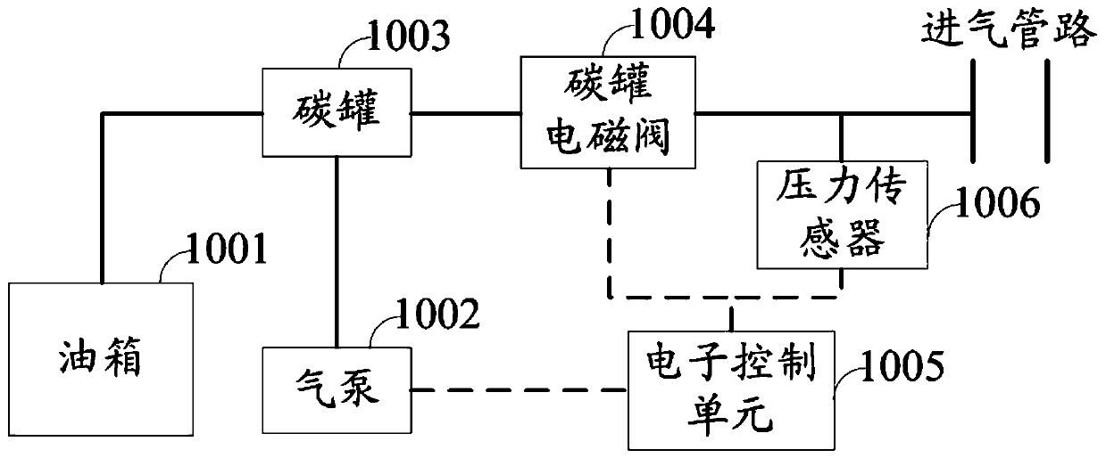
[0042] refer to figure 1 , figure 1 It is a schematic structural diagram of the fuel evaporation leakage detection system of the hardware operating environment involved in the solution of the embodiment of the present invention.

[0043] Such as figure 1 As shown, the fuel evaporation leakage detection system may include: a fuel tank 1001 , an air pump 1002 , a carbon canister 1003 , a carbon canister solenoid valve 1004 , an electronic control unit 1005 and a pressure sensor 1006 .

[0044] Those skilled in the art can understand that, figure 1 The structure shown in is not limited to the fuel evaporation leakage detection system, and may include more or less components than shown in the figure, or combine some components, or arrange different components.

[0045] The embodiment of the present invention provides ...


PUM


Abstract

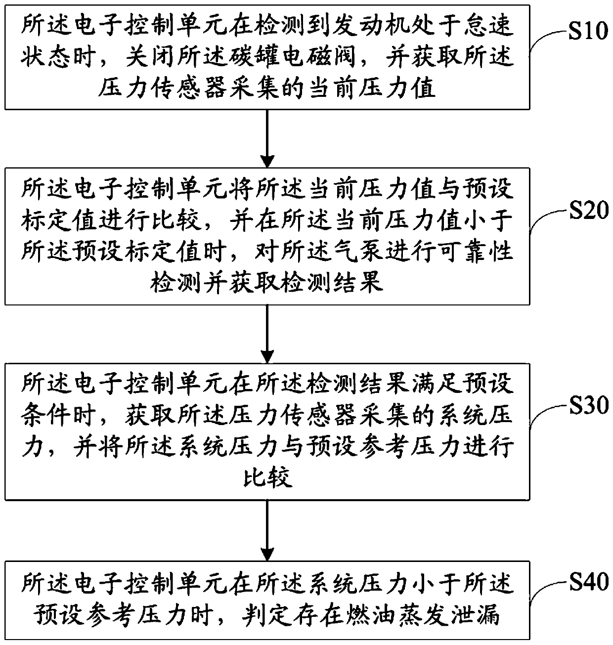
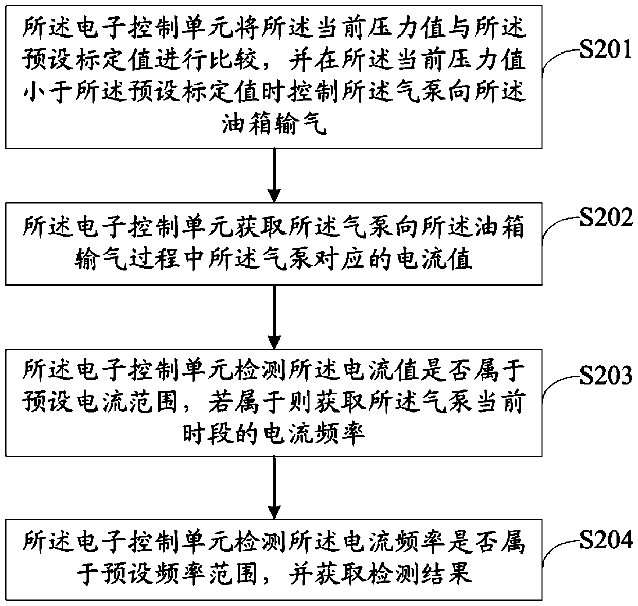
The invention discloses a fuel evaporation leak detection system and method. The system comprises an electronic control unit, an air pump, an oil tank, a carbon pot, a carbon pot electromagnetic valve, and a pressure sensor, wherein the electronic control unit turns off the carbon pot electromagnetic valve when detecting that a motor is at idle speed, acquires a current pressure collected by the pressure sensor and compares the current pressure with a preset calibration value, detects reliability of the air pump if the current pressure is less than the preset calibration value, and collects system pressure when a detection result meets a preset condition, and determines that fuel evaporation and leakage occur when the system pressure is less than a preset reference pressure. Through adoption of the system and method, the fuel pipeline is not vaccumized, so that leakage detection is less difficult; the carbon pot electromagnetic valve is turned off and then whether the electromagnetic valve fails is detected, if there is not fault, whether the air pump has a fault is detected, then, if the air pump has no fault, whether fuel evaporation and leakage occur is determined according to collected system pressure, therefore, a failed part can be positioned accurately, and leakage detection is more accurate.

Description

technical field [0001] The invention relates to the technical field of automobiles, in particular to a fuel evaporation leakage detection system and method. Background technique [0002] Among the whole parts of the car, the fuel system is a very important part. Due to the volatile nature of the gasoline in the fuel tank, the fuel tank is usually full of gasoline vapor at room temperature. In order to control the air pressure in the fuel tank, introduce gasoline vapor into the engine for combustion, and minimize the evaporation of gasoline vapor into the atmosphere when refueling, Onboard Refueling Vapor Recovery (ORVR) is usually used, that is, a carbon canister is installed between the engine and the fuel tank, and activated carbon is installed in the carbon canister. The activated carbon can absorb gasoline vapor, and the fuel tank and the carbon canister are in the same state. , gasoline vapor can enter the carbon tank through the pipeline, and the carbon tank also has ...

Claims


Application Information

Patent Timeline
Patent Type & Authority Patents(China)
IPC IPC(8): G01M3/26G01R31/00F04B51/00F02M25/08
CPCF02M25/08F04B51/00G01M3/26G01R31/00
Inventor 葛娟娟钟秋月李连杰胡璋林蒯家琛程剑峰李林
Owner ANHUI JIANGHUAI AUTOMOBILE GRP CORP LTD
Learn More