
Dynamic sealing device suitable for high speed and high pressure and aircraft

A dynamic sealing and aircraft technology, applied in the direction of engine sealing, rocket engine device, jet propulsion device, etc., can solve the problem that the sealing device cannot meet the long life, high reliability and repeated use, etc., to ensure the performance and meet the repeated use. , the effect of reducing the impact

Pending Publication Date: 2019-07-19
BEIJING XINGJI RONGYAO SPACE TECH CO LTD
View PDF0 Cites 7 Cited by
  • Summary
  • Abstract
  • Description
  • Claims
  • Application Information

AI Technical Summary

Problems solved by technology

[0006] The main purpose of the present invention is to provide a sealing device and an aircraft to solve or at least alleviate the sealing device in the prior art that cannot meet the requirements of long life, high reliability and repeatability under severe working conditions such as high speed, high pressure, and large temperature gradient. problem of use

Method used


Image

  • Dynamic sealing device suitable for high speed and high pressure and aircraft
  • Dynamic sealing device suitable for high speed and high pressure and aircraft
  • Dynamic sealing device suitable for high speed and high pressure and aircraft

Examples


Embodiment Construction

[0039] The technical solutions of the present invention will be clearly and completely described below in conjunction with the accompanying drawings. Apparently, the described embodiments are some of the embodiments of the present invention, but not all of them. Based on the embodiments of the present invention, all other embodiments obtained by persons of ordinary skill in the art without making creative efforts belong to the protection scope of the present invention.

[0040] In the description of the present invention, it should be noted that the terms "center", "upper", "lower", "left", "right", "vertical", "horizontal", "inner", "outer" etc. The indicated orientation or positional relationship is based on the orientation or positional relationship shown in the drawings, and is only for the convenience of describing the present invention and simplifying the description, rather than indicating or implying that the referred device or element must have a specific orientation, ...


PUM


Abstract

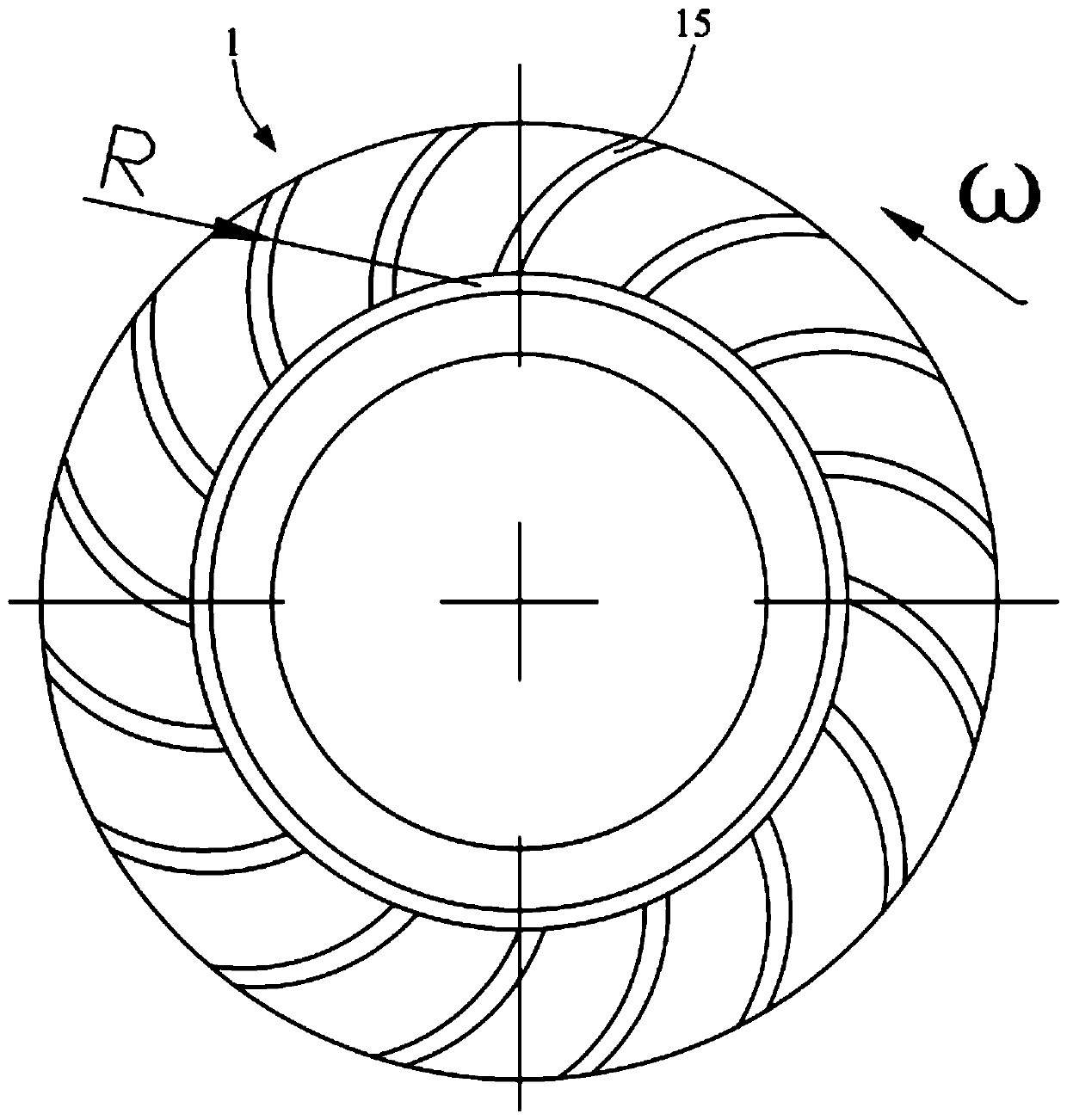
The invention relates to the technical field of sealing, in particular to a dynamic sealing device suitable for high speed and high pressure and an aircraft. The dynamic sealing device comprises a sealing shell, a rotating shaft, a liquid sealing wheel and a heat insulation sealing ring, wherein two cavities to be sealed are formed at intervals in the sealing shell, and a through hole making the two cavities communicate is formed in the sealing shell; the rotating shaft can rotate and at least partially penetrate through the through hole; the liquid sealing wheel is arranged on the rotating shaft, can rotate along with the rotation of the rotating shaft and can form a liquid seal between the rotating shaft and the sealing shell when rotating; and the heat insulation sealing ring is arranged between the rotating shaft and the sealing shell and is close to the liquid sealing wheel, and a combined seal is formed between the heat insulation sealing ring and the liquid sealing wheel; the rotating shaft which rotates at a high speed enables the liquid sealing wheel to form a liquid seal between the sealing shell and the rotating shaft, a blocking effect can be achieved for high pressure,the heat insulation sealing ring can achieve a high-temperature insulation effect, the influence of the high temperature on the whole dynamic sealing device is greatly reduced, so that the reliability and the service life of the dynamic sealing device are improved under severe working conditions of high rotating speed, high pressure, and large temperature gradient.

Description

technical field [0001] The invention relates to the technical field of sealing, in particular to a dynamic sealing device suitable for high speed and high pressure and an aircraft. Background technique [0002] At present, the world has entered the trend of commercial aerospace development, and high reliability, low cost, reusable, and pollution-free rocket engines have become the development direction of liquid rocket engines. Among them, the liquid oxygen methane engine in the rocket has good cooling performance, high combustion efficiency, is not easy to coke, and has a higher specific impulse than the liquid oxygen kerosene engine, and the fuel cost per unit mass of methane is only 1 / 3 of kerosene and 1 / 30 of liquid hydrogen. It has been widely used in aerospace field. [0003] As an important part of the liquid oxygen methane engine, the methane pump is used to deliver the low-temperature liquid methane required for the engine to work. The methane pump is located next ...

Claims


Application Information

Patent Timeline
IPC IPC(8): F16J15/30F16J15/40F02K9/60
CPCF16J15/30F16J15/40F16J15/164F02K9/60
Inventor 不公告发明人
Owner BEIJING XINGJI RONGYAO SPACE TECH CO LTD
Learn More