
Automatic mechanical clipping and cutting equipment

A technology of equipment and machinery, applied in the field of cutting equipment, can solve the problems of small adjustment range of moving work, falling out of mechanical parts, large friction loss, etc.

Active Publication Date: 2019-07-19
安徽人和智能制造有限公司
View PDF7 Cites 4 Cited by
  • Summary
  • Abstract
  • Description
  • Claims
  • Application Information

AI Technical Summary

Problems solved by technology

[0005] The purpose of the present invention is to solve the problem that the existing mechanical cutting equipment cannot be flexibly adjusted to cut the position and angle of the mechanical parts, and the efficiency of the staff to adjust the working position of the cutting equipment is slow, and the equipment can be adjusted The range of mobile work is very small, and the efficiency of cutting and cutting of mechanical parts by the equipment is slow, the quality is poor, the precision of cutting and cutting is low, and the cutting and cutting position of the equipment is not stable and reliable when adjusted to the cutting and cutting position of the mechanical parts, resulting in the parts on the equipment The friction loss between them is large, the service life of the equipment is low, and after the equipment cuts the mechanical parts, the mechanical parts are easy to fall out from the conveying line, and an automatic mechanical cutting equipment is proposed

Method used


Image

  • Automatic mechanical clipping and cutting equipment
  • Automatic mechanical clipping and cutting equipment
  • Automatic mechanical clipping and cutting equipment

Examples


Embodiment Construction

[0053] The technical solutions of the present invention will be clearly and completely described below in conjunction with the embodiments. Apparently, the described embodiments are only some of the embodiments of the present invention, not all of them. Based on the embodiments of the present invention, all other embodiments obtained by persons of ordinary skill in the art without creative efforts fall within the protection scope of the present invention.

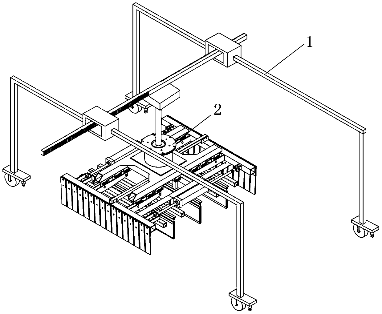
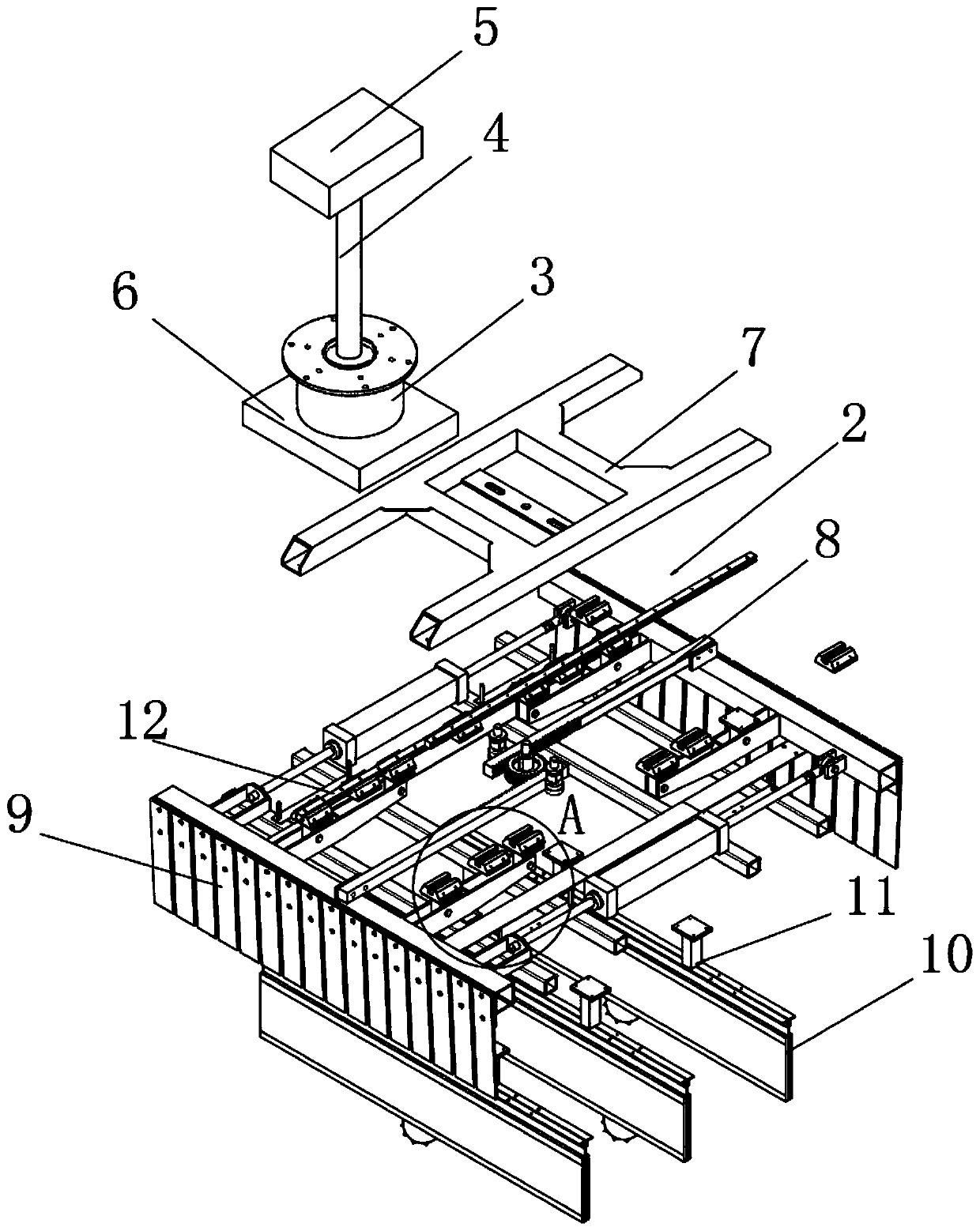
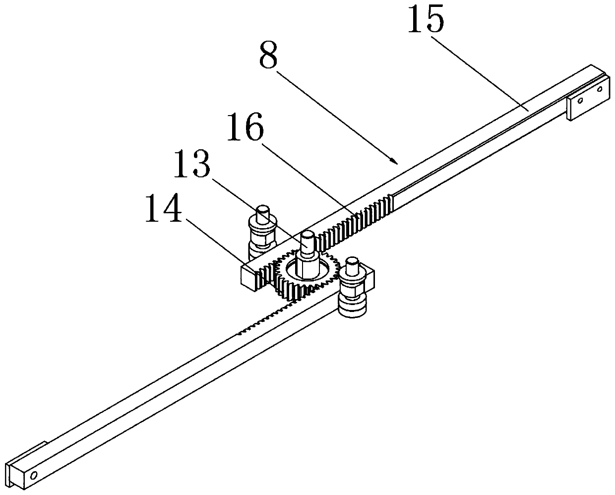
[0054] see Figure 1-16 As shown, an automatic mechanical cutting equipment includes a frame platform 1, a working disc 2, a first motor 5 and three cutting frames 10, a working disc 2 is vertically arranged under the middle part of the frame platform 1, and the top of the working disc 2 is arranged There is a first motor 5, a first hydraulic rod 4 is arranged vertically below the first motor 5, and the bottom of the first hydraulic rod 4 is connected to the inside of the first hydraulic pump 3, and the bottom of the first ...


PUM


Abstract

The invention discloses automatic mechanical clipping and cutting equipment. The equipment comprises a frame table, a working disc, a first motor and three cutting frames, wherein the working disc isvertically arranged below the middle of the frame table; the first motor is arranged at the top of the working disc; and a first hydraulic rod is vertically arranged below the first motor. Second gears are respectively driven by two third motors to roll in two first rolling grooves and are matched with a plurality of second gear hobbings to roll, so that cutting blades are adjusted to move back and forth more stably and smoothly in the cutting frames, and it is ensured that the cutting blades are moved and adjusted more accurately while shaking of the cutting blades and friction collision between the cutting blades and components on the cutting frames are both reduced. Two fourth motors separately roll in second rolling grooves through first rollers to drive the cutting frames and the cutting blades to be moved left and right for adjustment, so that the cutting blades clip and cut a mechanical object more accurately, and the quality of clipping and cutting a mechanical part by the equipment is improved.

Description

technical field [0001] The invention relates to a cutting device, in particular to an automatic mechanical cutting device, which belongs to the technical field of mechanical cutting device application. Background technique [0002] With the rapid development of people's living standards, cutting equipment is becoming more and more indispensable in the production and processing of mechanical parts. The main function of cutting equipment is to cut and cut mechanical parts so that mechanical parts can be processed into required specifications or sizes. The shape is convenient for the later use of mechanical parts, and the cutting equipment greatly speeds up the efficiency of cutting and processing of mechanical parts, which is favored by people. [0003] The Chinese patent with publication number CN206663384U discloses a kind of cutting equipment for mechanical processing, including RS-hydraulic controller, support, KG-photoelectric induction controller electric retractor, indu...

Claims


Application Information

Patent Timeline
Patent Type & Authority Applications(China)
IPC IPC(8): B23D79/00B23Q7/00B23Q5/34
CPCB23D79/00B23Q5/34B23Q7/00
Inventor 李光明
Owner 安徽人和智能制造有限公司
Learn More