
Device for measuring outer side soil pressure of shield tunnel

A technology of shield tunneling and measuring devices, which is applied in the direction of measuring devices, force/torque/work measuring instruments, instruments, etc., which can solve measurement errors and fail to ensure that the outer membrane of the earth pressure box is in good contact with the test soil, and the earth pressure Issues such as box embedding state influence

Active Publication Date: 2019-07-16
TIANJIN UNIV
View PDF7 Cites 4 Cited by
  • Summary
  • Abstract
  • Description
  • Claims
  • Application Information

AI Technical Summary

Problems solved by technology

[0006] 2. Influenced by the size of the earth pressure cell
[0008] 3. Affected by the buried state of the earth pressure box
[0009] The earth pressure cell is pre-buried in the prefabricated segment, and along with the production process of the prefabricated segment, it goes through the curing stage together, resulting in uneven pressure distribution on the outer membrane of the earth pressure cell and resulting in measurement errors; During the soil contact process, it cannot be guaranteed that the outer membrane of the earth pressure cell is in good contact with the test soil
[0010] 4. Affected by the sensor itself
[0011] The earth pressure cell is greatly affected by environmental factors. The indoor air humidity is required to be less than 80%, no corrosive gas and ventilation conditions, and it is required to be handled with care when handling. The earth pressure cell that has not been used for a year needs to be re-calibrated; During the test, the zero point of the earth pressure cell will drift with time, so it is not suitable for long-term monitoring of earth pressure

Method used


Image

  • Device for measuring outer side soil pressure of shield tunnel
  • Device for measuring outer side soil pressure of shield tunnel
  • Device for measuring outer side soil pressure of shield tunnel

Examples


Embodiment Construction

[0028] The technical solutions of the present invention will be described in detail below in conjunction with specific embodiments and drawings, but the protection scope of the present invention is not limited to the following embodiments.

[0029] In combination with the above-mentioned drawings, an implementation case of the earth pressure measurement device on the outside of the tunnel is proposed.

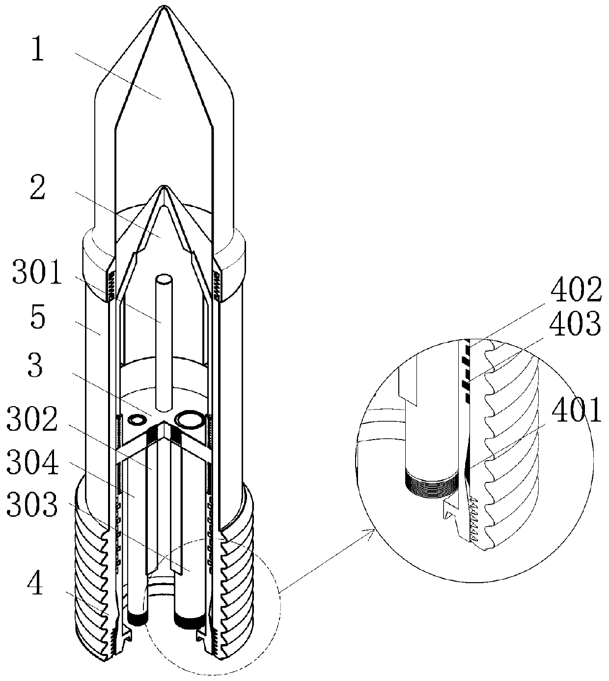
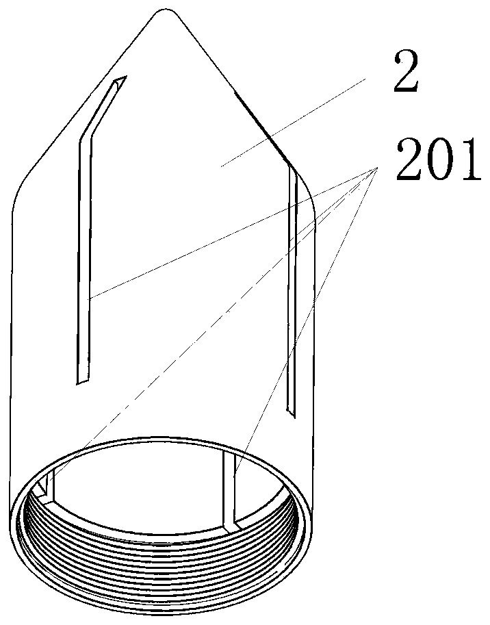
[0030] Such as figure 1 As shown, the earth pressure measuring device outside the shield tunnel of the present invention includes a TPU oil bag 1, the "upper" part 2 of the piston, a set pair wire 3, a heating rod 301, a pressure liquid level set temperature transmitter 302, an oil delivery pipe 303, Exhaust pipe 304, stainless steel cylinder 4, water-expandable rubber sleeve 5, piston "lower" part 6, silicone O-ring 7, piston installation support part 8, earth pressure measurement device installation support part 9.

[0031] The main function of the TPU oil bladder 1 is to se...


PUM


Abstract

The invention relates to a device for measuring outer side soil pressure of a shield tunnel. The device comprises an oil bag, a silica gel O-shaped sealing ring, a water swelling rubber sleeve, a cylinder barrel, a piston, a steel wire rope used for pulling the piston, a piston mounting supporting part used for mounting, an electric control system and an oil supply unit, wherein the oil bag is used for sensing soil body deformation and transmitting the soil pressure and engaged with the cylinder barrel through a thread, and compresses the silica gel O-shaped sealing ring to seal hydraulic oil;an outer thread and an inner thread are arranged on the lower part of the cylinder barrel, the outer thread is matched with an inner thread of a hoisting grouting hole, and the inner thread is connected with the piston mounting supporting part; a convex groove used for fixing the piston is formed in the lower position of the cylinder barrel, threads at the bottom and the top of the cylinder barrel are opposite in direction, and the thread at the bottom of the cylinder barrel and the inner thread of the hoisting grouting hole are the same in direction; and the piston is located in the cylinderbarrel and comprises an upper piston part, a formulating nipple, a heating rod, a pressure liquid level assembled temperature transmitter, an oil delivery pipe, an exhaust pipe and a lower piston part.

Description

technical field [0001] The invention belongs to the technical field of geotechnical engineering testing, and relates to an outer earth pressure measuring device of a shield tunnel. Background technique [0002] The continuous advancement of the country's modernization process requires cities to accommodate a large enough urban population, and the construction and improvement of urban infrastructure ensures the city's high-speed operation and employment capacity. The planning and development of urban rail transit has led to the construction of a large number of subway tunnels. Among them, the shield tunneling method has many advantages such as fast construction speed, high degree of automation, small impact on the environment, and mature industry and technology. It is the preferred method for subway tunnel construction. The shield tunnel is composed of lining segments and joint structures. The lining structure is in direct or indirect contact with the soil through the groutin...

Claims


Application Information

Patent Timeline
IPC IPC(8): G01L5/00
CPCG01L5/0028
Inventor 张稳军高文元张高乐丁超李宏亮卢权威王祎上官丹丹
Owner TIANJIN UNIV
Learn More