Wiper speed regulating control method, system and controller
A control method and control system technology, which is applied in the direction of single motor speed/torque control, vehicle cleaning, vehicle maintenance, etc., and can solve problems such as difficulty in adjusting the reverse speed of the wiper
- Summary
- Abstract
- Description
- Claims
- Application Information
AI Technical Summary
Problems solved by technology
Method used
Image
Examples
Embodiment 1
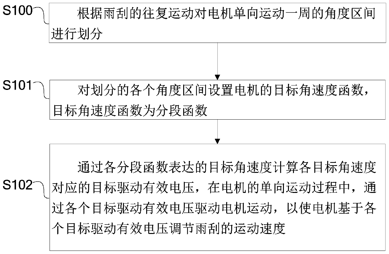
[0035] For the above application scenarios, this example provides a speed control method for wipers. The design idea of this method is: convert the one-way motion of the motor into the reciprocating motion of the wiper, and control the motor during the one-way motion of the motor The target drive effective voltage, so that the motor adjusts the movement speed of the wiper based on the target drive effective voltage.
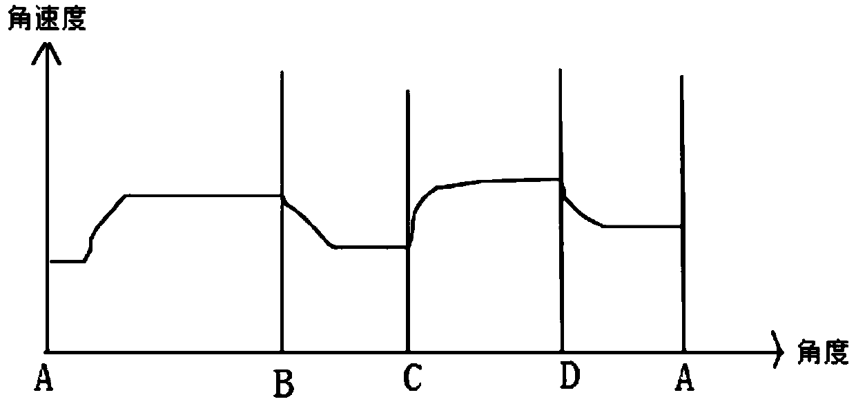
[0036] Through the above-mentioned design idea, in the process of driving the wiper to and fro by the motor in one direction, the driving effective voltage of the motor is controlled, and then the variable speed movement of the wiper is controlled, for example, the wiper can be slowed down near the reversal point, The middle area controls the accelerated operation of the wiper in a certain way to increase the wiping speed, so as to ensure that the running speed of the wiper can be adjusted in the entire wiping cycle, reduce the elastic deformation of the wiper b...
Embodiment 2
[0073] Based on Embodiment 1, this example provides a wiper speed control system, the control principle of which is Figure 4 As shown, the schematic diagram of the circuit is shown in Figure 5 shown.
[0074] Including motor, induction module and control module, wherein, the motor is connected with the wiper through the connecting rod structure, and the one-way motion of the motor is converted into the reciprocating motion of the wiper through the connecting rod structure. Regarding the connecting rod between the motor and the wiper The structure and the reciprocating movement of the wiper are well known to those skilled in the art, and will not be described in detail in this example.
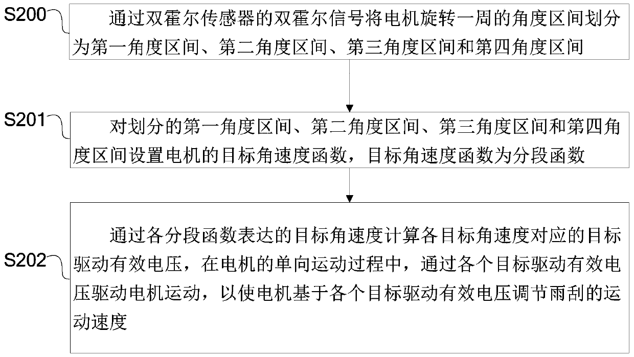
[0075] The induction module is installed with the motor, and the induction module is used to sense four sets of signals according to the one-way movement of the motor;
[0076] The control module is electrically connected to the motor, and the control module performs the following operation...
Embodiment 3
[0116] Based on the first and second embodiments, this example provides a wiper speed control controller, including a control module and a sensing module; wherein, the control module has the same structure as the control module in the second embodiment, and the sensing The structure of the module is the same as that of the induction module in the second embodiment, and the specific structures of the control module and the induction module will not be repeated in this example.
[0117] The induction module is installed with the motor, and the induction module is used to sense four sets of signals according to the one-way movement of the motor;
[0118] The control module is electrically connected to the motor, and the control module performs the following operations to control the target driving effective voltage of the motor, so that the motor can adjust the moving speed of the wiper based on the target driving effective voltage:
[0119] Divide the angle interval of one revol...
PUM
 Abstract
Description
Claims
Application Information
 - R&D Engineer
- R&D Manager
- IP Professional
- Industry Leading Data Capabilities
- Powerful AI technology
- Patent DNA Extraction
Browse by: Latest US Patents, China's latest patents, Technical Efficacy Thesaurus, Application Domain, Technology Topic, Popular Technical Reports.
© 2024 PatSnap. All rights reserved.Legal|Privacy policy|Modern Slavery Act Transparency Statement|Sitemap|About US| Contact US: help@patsnap.com


